10.6.8 Isolated Patient Lead (Sink) Leakage-Isolation Test
Select the ALL position on the LEAD selector since the test is performed with mains applied to all ECG leads
at the same time.
Caution
Line voltage is applied to the ECG leads during this test. To avoid possible electric shock hazard, the system
being tested must not be touched by patients, users or anyone while the ISO TEST switch is depressed.
10.6.8.1 Isolated Lead (Sink) Leakage Test Record
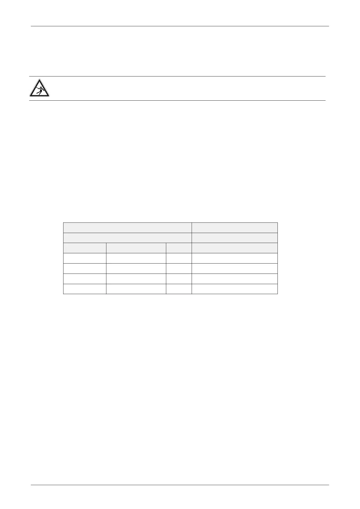
Table 10-16
shows a typical format for recording the isolated patient lead sink leakage current.
Measurements should be recorded for full lead combination under each set of test conditions specified in:
•
Table 10-11 on page 10-11
Record all data and keep the record of the results with other hard copies of maintenance data.
1. Connect the Safety analyzer to an AC wall outlet.
2. Plug the equipment under test into the receptacle on the panel of the meter.
3. Connect the ECG cable to the Voluson E-Series system and the patient leads to the analyzer.
4. Select the "Patient Lead Leakage" function on the meter.
5. Test with closed ground with the Voluson E-Series system on and off.
Note
For more information, refer to the safety analyzer's user manual that will be used to perform the test.
Table 10-16 Typical Data Format for recording Isolated Patient Lead (sink) Leakage
Unit under Test: Date of Test:
Test Conditions Patient Lead
System Power Grounding/PE Limit μA
RA+LA+LL
on closed 50
off closed 50
on closed (reversed polarity) 50
off closed (reversed polarity) 50
Note
Values in italics font are given as examples only.
Care and Maintenance
10-18
Voluson E-Series Service Manual
5539550APB Revision 6