3.4.3 Probe Connection
Note
When the probe is connected, it is automatically activated. Once connected, probes can be selected for
different applications.
Connect a probe to one of the three rightmost probe receptacle as follows:
1. Inspect the probe and probe socket to verify that it is free of debris.
2. Ensure that the probe locking lever is at horizontal position.
3. Insert the connector on the receptacle guide pin until it touches the receptacle mating surface.
4. Twist the probe locking lever clockwise (to vertical position) to lock it in place.
5. Open the side door, lay the cable into the intended cable holder and close the door.
6. Carefully position the probe cord so that it is free to move and is not resting on the floor.
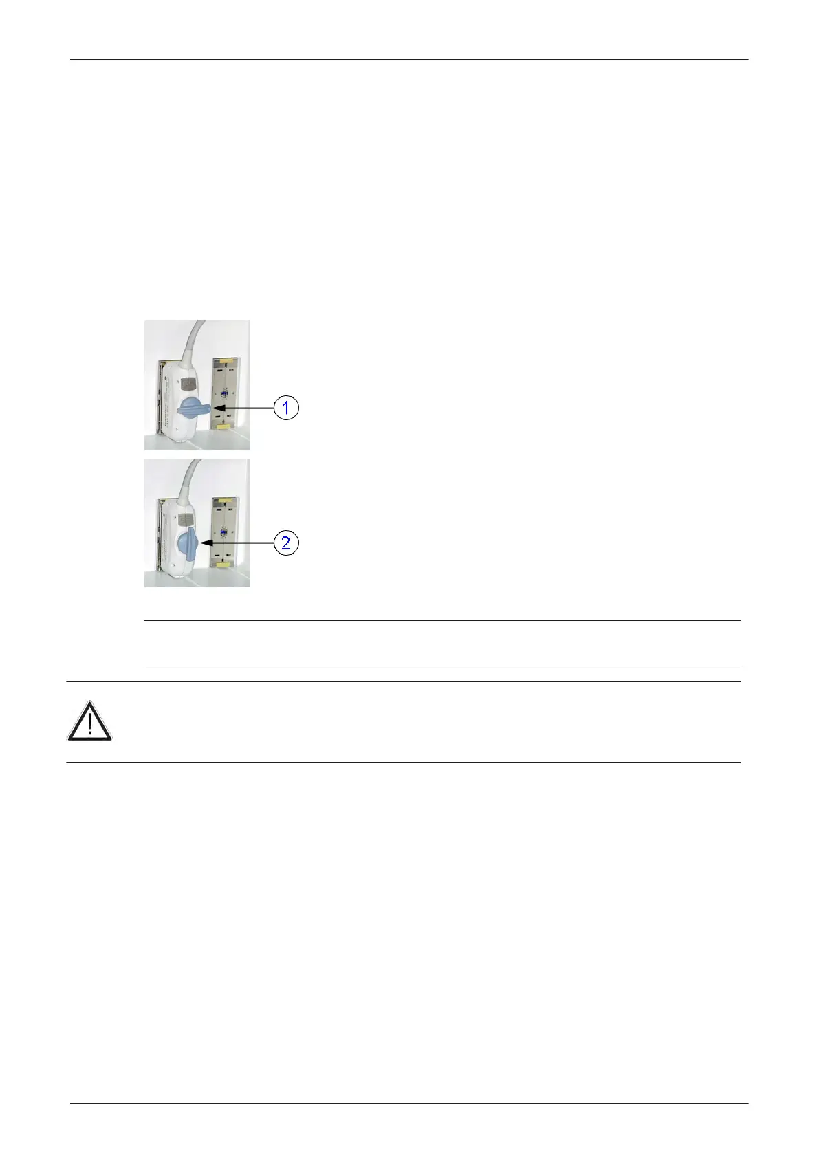
Figure 3-8 probe connection
1 probe unlocked
(locking lever is in horizontal position)
2 probe locked (locking lever is in vertical position)
Caution
•
Do not bend the probe cable acutely. Fault conditions can result in electric shock hazard.
•
Do not touch the surface of probe connectors which are exposed when the probe is removed.
•
Do not touch the patient when connecting or disconnecting a probe.
Note
Prior to connecting or disconnecting a probe, freeze the image. It is not necessary to turn OFF power to
connect or disconnect a probe.
Setup Instructions
Voluson E-Series Service Manual
5539550APB Revision 6
3-13