3.9.1 External I/O Pin Outs
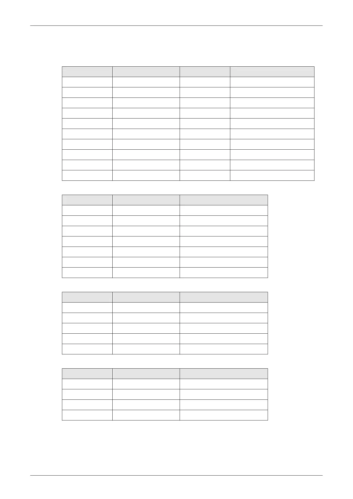
Table 3-7 HDMI OUT connector
Pin No Signal Pin No Signal
1 TDMS Data2+ 11 TMDS Clock Shield
2 TDMS Data2 Shield 12 TMDS Clock-
3 TDMS Data2- 13 CEC
4 TDMS Data1+ 14 Reserved/HEC Data-
5 TDMS Data1 Shield 15 SCL (Serial Clock for DDC)
6 TMDS Data1- 16 SDA (Serial Data Line for DDC)
7 TMDS Data0+ 17 DDC/HEC/CEC Ground
8 TMDS Data0 Shield 18 +5V Power
9 TDMS Data0- 19 Hot Plug Detect/HEC Data+
10 TMDS Clock+
Table 3-8 VGA OUT connector, Sub-D (15 pin)
Pin No Output Signal Description
1 VGA OUT1 R Red
2 VGA OUT1 G Green
3 VGA OUT1 B Blue
4, 9, 11, 12, 15 N/C N/C
5, 6, 7, 8, 10 GND GND
13 VGA OUT1 HS H Sync
14 VGA OUT1 VS V Sync
Table 3-9 Network connector, RJ45 Modular (8 pin)
Pin No Output Signal Description
1 ETHER TD Ethernet RD +
2 ETHER TD Ethernet RD -
3 ETHER RD Ethernet TD +
6 ETHER RD Ethernet TD -
others NC no connection
Table 3-10 USB 2.0 connectors
Pin No Output Signal Description
1 VCC USB Power Supply
2 - Data USB Data (-)
3 + Data USB Data (+)
4 GND USB Power Ground
Setup Instructions
3-52
Voluson E-Series Service Manual
5539550APB Revision 6