7.3 Check Point Voltages
7.3.1 User Interface - Status LEDs
The LED within the start key (ON/OFF
button) on the User Interface is used to signal the status of the
Voluson E-Series system.
The following states are implemented:
Orange System in standby mode.
Green System in normal operation mode.
blinking
Orange <=> Green
FPGA_CONF_DONE = low
IF-FPGA not initialized -> probably FrontEnd (RFM board) or Power Supply
(RSP) issue
NO light System is switched OFF (circuit breaker)
NO light probably Power Supply (RSP) defect
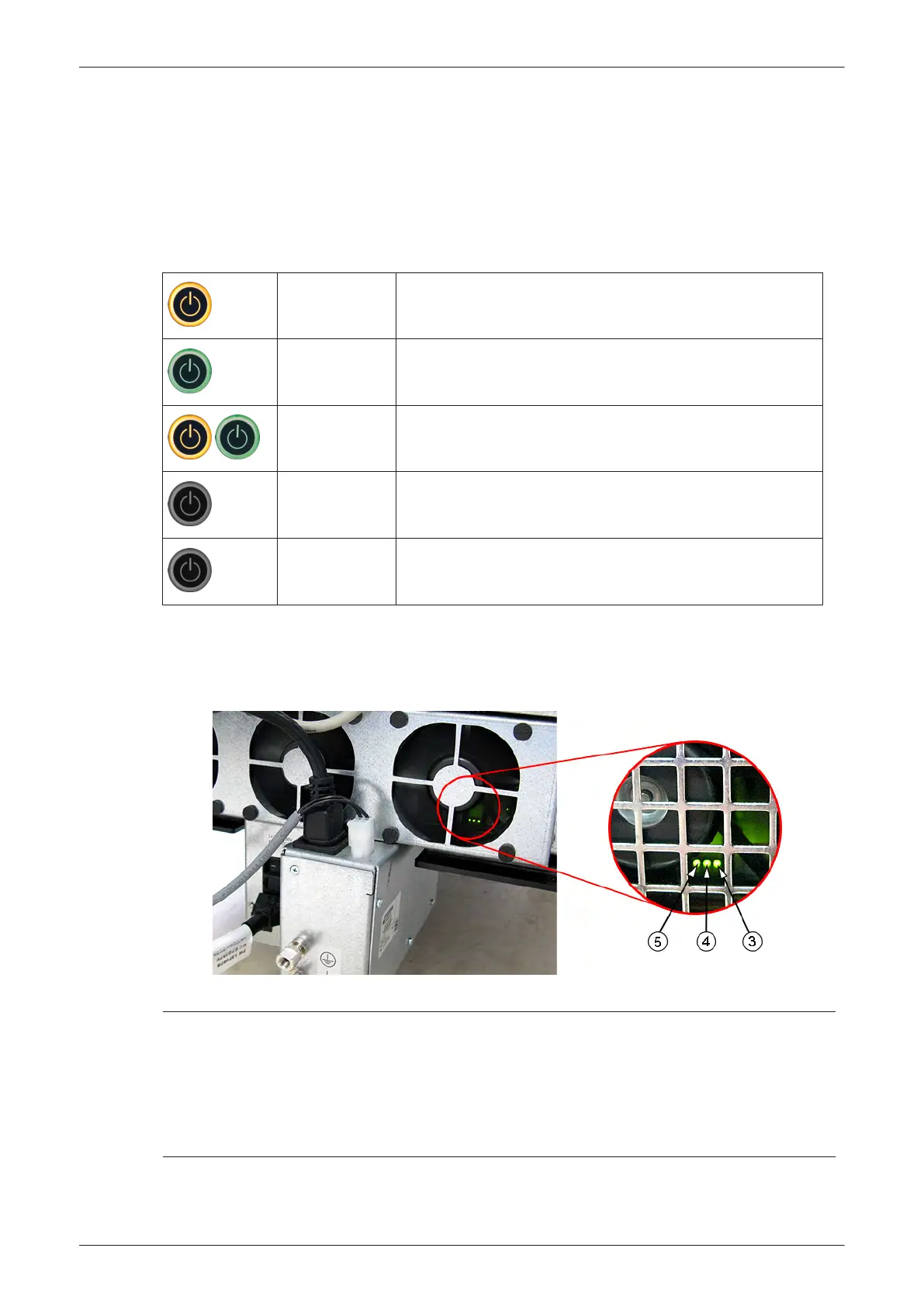
7.3.2 Power Supply (RSP) Status LEDs
On the backside of the ATX board near the fans 3 green status LEDs are mounted. These LEDs are used for
signaling the status of the Power Supply (RSP).
Figure 7-6 check green LEDs inside RSP
LED 3 Off: 12V_FE off
On: 12V_FE on
LED 4 Off: FPGA_CONF_DONE = low
On: FPGA_CONF_DONE = high
LED 5 Off: ATX supply off
On: ATX supply on
Diagnostics/Troubleshooting
Voluson E-Series Service Manual
5539550APB Revision 6
7-7