137
Program description - Dual Rate / Expo | Helicopter models
Exponential function
If a switchover between two variants is desired, as-
sign a switch in the column labeled with the
switch symbol (as described in the section "Assigning
transmitter controls, switches and control switches"
on page 60).
0%
0%
0%
Roll
Pitch ax
Tail rot
DUAL
–––
–––
SEL
–––
–––
–––
100%
100%
100%
EXPO
SEL
Move desired switch
to ON position
(ext. switch: ENTER)
Normal
3
If necessary, this may also be one of the transmitter
control switches C1 … C8 or C1i … C8i or one of the
logical switches L1 … L8 or L1i … L8i from the list of
"expanded switches".
The switch so assigned appears on the display, to-
gether with a switch icon that indicates the switch's
switching direction.
In the case of "C" or "L" switches, the stick or another
transmitter control or a certain switching logic can
itself be used as a switch. However, such a control
switch must have been appropriately defined in the
»Control switch« menu, see page 119, and a logical
switch must have been appropriately defined in the
»Logical switch« menu, see page 150.
Whichever switch has been assigned … the respec-
tive switch appears on the display together with a
switch icon that indicates the switch's respective
direction when moved.
0%
0%
0%
Roll
Pitch ax
Tail rot
DUAL
––––––
–––
SEL
–––
–––
–
100%
100%
100%
EXPO
SEL
Move desired switch
to ON position
(ext. switch: ENTER)
Normal
If necessary, this may also be one of the transmitter
control switches C1 … C8 or C1i … C8i or one of the
logical switches L1 … L8 or L1i … L8i from the list of
"expanded switches".
The switch so assigned appears on the display, to-
gether with a switch icon that indicates the switch's
switching direction.
In the case of "C" or "L" switches, the stick or another
transmitter control or a certain switching logic can
itself be used as a switch. However, such a control
switch must have been appropriately defined in the
»Control switch« menu, see page 119, and a logical
switch must have been appropriately defined in the
»Logical switch« menu, see page 150.
Whichever switch has been assigned … the respec-
tive switch will appear in the display together with a
switch symbol indicating the switch's direction if actu-
ated, e. g. in the «Normal» flight phase.
0%
0%
0%
Roll
Pitch ax
Tail rot
DUAL
–––
–––
SEL
–––
–––
–––
100%
100%
100%
EXPO
SEL
3
Normal
Once the value field has been activated with a brief
tap on the SET key of the right touch pad, use the se-
lection keys of the left or right touch pad to move into
the Dual-Rate value column labeled SEL at the bot-
tom edge of the display in order to separately change
the dual-rate values shown in inverse video for each
of the two switch positions.
0%
0%
0%
Roll
Pitch ax
Tail rot
DUAL
–––
–––
SEL
–––
–––
–––
100%
100%
EXPO
SEL
3
Normal
111%
0%
0%
0%
Roll
Pitch ax
Tail rot
DUAL
–––
–––
SEL
–––
–––
–––
100%
100%
EXPO
SEL
3
Normal
88%
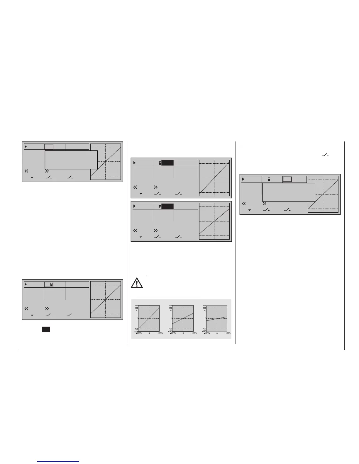
At the same time, the Dual-Rate curve will be pre-
sented in the graph. A simultaneous tap on the or
keys of the right touch pad (CLEAR) will reset a
changed entry field value displayed in inverse video
back to "100 %".
Caution:
For safety reasons, Dual Rate value settings
should not be less than 20 %.
Some examples of Dual Rate values:
Servo travel
Servo travel
Servo travel
Stick deflection
Stick deflection
Stick deflection
Dual Rate = 100%
Dual Rate = 50%
Dual Rate = 20%