182
Program description - Wing mixers
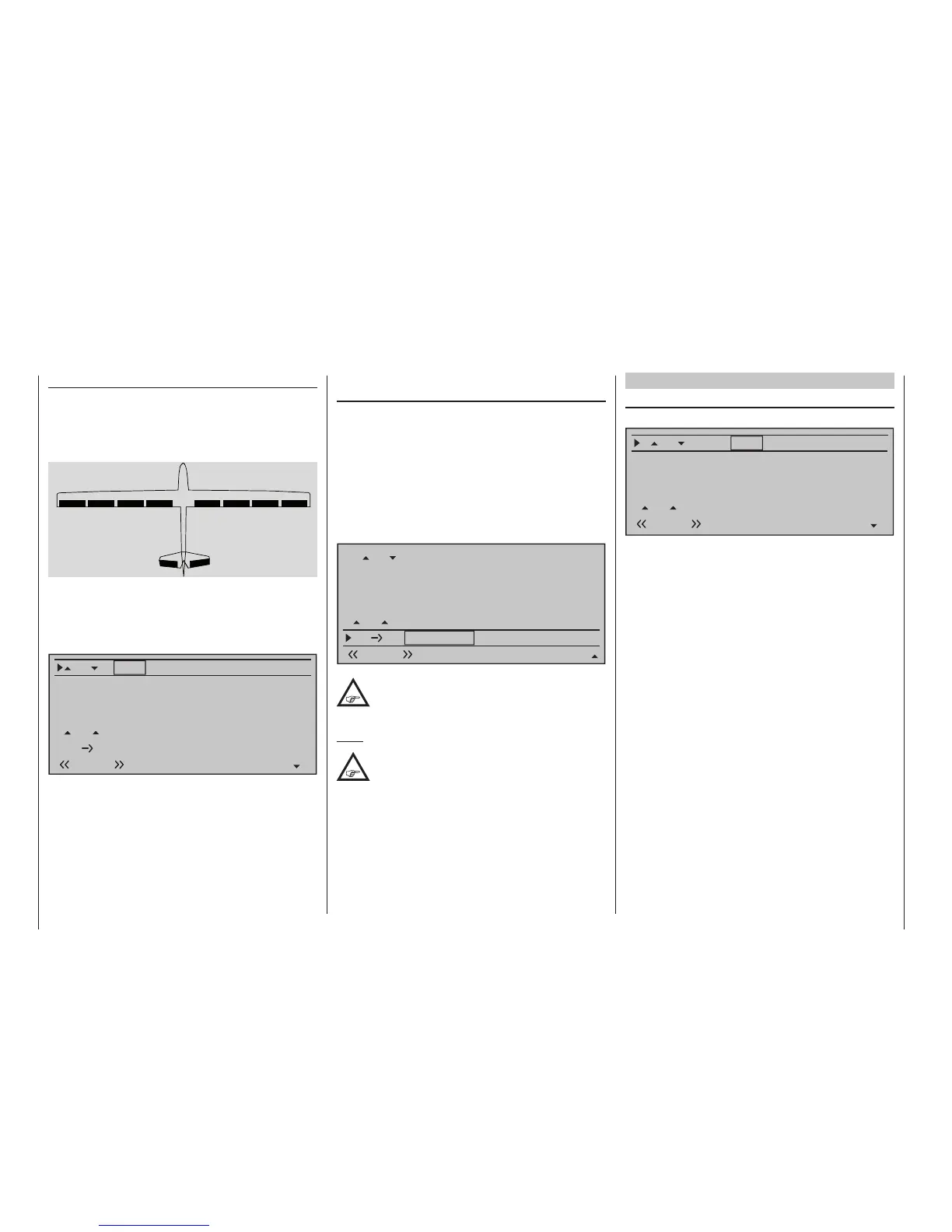
Model type: "4AIL 4FL"
If servos have been connected to the receiver as
described on page 65 and selected accordingly in the
»Model type« menu, page 105, then the abbrevia-
tions "AILE", "AILE2", "FLAP" and "FL2" refer to the
following flaps:
AI
left
AI2
left
FL
left
FL2
left
FL2
right
FL
right
AI2
right
AI
right
Since the "4AIL 4FL" selection represents the maxi-
mum possible number of wing servos, in addition to
the columns labeled "AILE" and "AILE2" there will
now also be columns available labeled "FLAP" and
"FL2.
Fl.pos
Diff.
Ail-tr
AI
Normal AILE
+100%
FL2
0 0%+100+100%+100+100%+100+100%
0%
0%
0%0%
0%
0%
0%
+100%
0%
0%
0%
FL
AILE2
FLAP
+100%
+100%
0%
0%
El
Fl
0 0%+100+100%+100+100%+100+100%
Delta/ying wing type models with more than two
wing aps
If you have selected the “Delta/fl“ tail type and se-
lected the number of wing flaps in the “Aile/flaps” line
on the »Model type« menu (following the instruc-
tions given in that section on page 105), then the two
ailerons will normally not move when you move the
elevator stick – and the same will be true for the inner
flaps (FL) and FL2 (if present). The reason for this is
the default mixer ratio of 0% for all wing flaps, set for
the “EL FL” mixer that is to be found on the multi-
flap menu:
Fl.pos
Diff.
Ail-tr
Al
Normal AILE
+100%
FLAP
0%
0%
0%
+100%
0%
+100%
0%
+100%
0%
0%
0%0%
+100%
0%
0%
0%
FL
El
Fl
+100%
+100%
+100%
+100%
0%0%
0%
0%
0%0%
0%
0%
Accordingly, you must first specify your de-
sired elevator control on the "EL FL" line.
Take care to ensure that up/down activation
occurs in the right sequence.
Note:
The "Brake settings" sub-menu is also
suitable for setting up the buttery (crow)
function with delta and ying wing models. In
ne-tuning the deection of the ap pairs AIL, FL and
(if present) AIL2 and/or FL2, however, ensure that the
moments created by one pair of aps compensate
the moments created by the other pair of aps in
each case. For example: the "up" effect of ailerons
when deected up should be compensated by a
"down" effect from aps when they are lowered.
Multi-ap menu
AI (Aileron camber flaps)
(suppressed by "2AIL 1FL")
Fl.pos
Diff.
Ail-tr
Al
Normal AILE
+100%
FL2
FLAP
0%
0%
0%
+100%
0%
+100%
0%
+100%
0%
0%
0%0%
+100%
0%
0%
0%
FL
+100%
+100%
0%
0%
0%0%
The “AI“ line can be used to make flight-phase
dependent settings for the percentage of aileron ac-
tion to result for the camber flap pair "FLAP" and, if
present, also "FL2" when aileron control is exercised.
(In the "AILE" and, if present, “AILE2” column it is
also possible to adjust the deflection of the aileron
pair, if required.) Normally, however, the flaps should
follow the ailerons with less of a deflection, i. e. the
mixer ratio should be smaller than 100 %.
The adjustment range of -150 % to +150 % means
the direction of deflection can be adjusted, depending
on the direction of rotation of the servos, to suit the
ailerons.
A simultaneous tap on the or keys of the
right touch pad (CLEAR) will reset the given active
(inverse video) field to its default value shown in the
figure.