186
Program description - Wing mixers
0%
+100%I9
I10
I11
I12
Ty p
SEL
+100%
0.0 0.0
– travel + –time+
0%
+100%
+100%
0.0 0.0
0%
+100%
+100%
0.0 0.0
0%
+100%
+100%
0.0 0.0
GL
GL
GL
Cn1 ---
fr
fr
fr
---
---
---
offset
GL
Normal
As you do, leave the settings for offset, travel,
etc. at their default values. Also leave the default
"GL" value in the column labeled "TYP" so that
the second airbrake, like the rst, operates in the
same way across all ight phases.
AI
FL
FL
AI
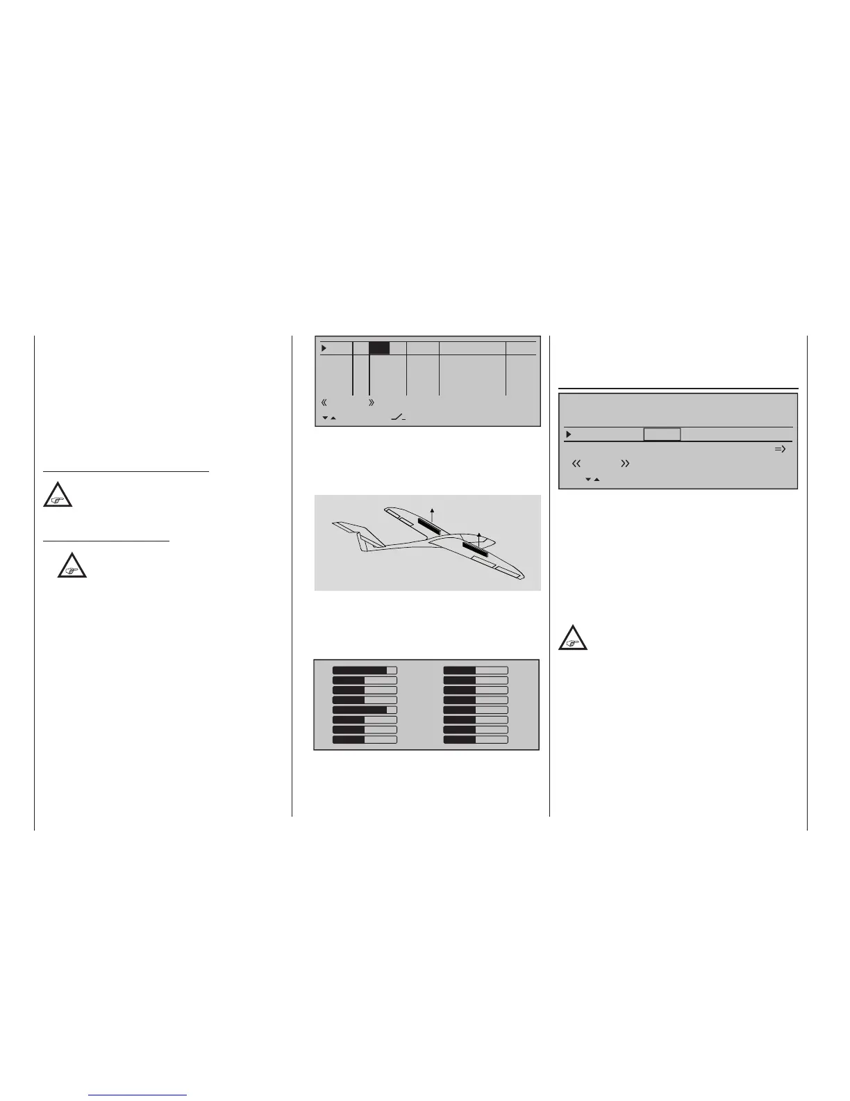
Servo 1
Servo 9
You can assure yourself that this works as stated
by accessing the »Servo display« menu,
accessible from almost any menu level with a brief
simultaneous tap on the keys on the left touch
pad (see page 282):
1
3
5
7
9
11
13
15
0
0
0
0
0
0
0
0
+100
0
0
0
+100
0
0
0
2
4
6
8
10
12
14
16
If this relatively simply variant should prove
impossible for whichever reasons, then the
alternative is a solution with two free mixers – and
potentially involving the »Mix only channel«
menu, page 221.
In either case, however, the airbrake travels must
then be ne-tuned on the »Servo adjustment«
menu, page 112.
Diff. reduct
Elevat. curve
BRAKE SETTINGS
Normal
Crow
AILE
0%
WK2
0%
FLAP
0%
Diff. reduct
FL2
0%
0%
0%
Earlier, we discussed the problems with the butterfly
(crow) configuration. Namely: that with the use of
aileron differential, the aileron effect can be strongly
(negatively) affected by the aileron elevation. This is
firstly because further deflection of the one aileron
upwards is (almost) no longer possible and secondly
because the downward-deflected aileron – depend-
ing on the elevation and degree of differential con-
figured – is often unable to achieve even its "normal"
position.
To be able to restore the effect of the aileron
altered in this way as far as possible, you
should ensure that you make use of the
automated "Differential reduction" feature. This fea-
ture continuously reduces the degree of aileron differ-
ential as the airbrake system is extended. The feature
is configurable and can even be set to suppress
differential entirely.
A value of 0 % means that the "aileron differential" set
at the transmitter remains fully in force. An entry that
equals the % value set for aileron differential means
the differential is fully eliminated once the butterfly
function is at maximum travel, i. e. with flaps fully
extended. Setting a reduction value greater than the
aileron differential configured will eliminate the latter
even before the full travel of the airbrake stick.
move moderately upward while the aps move
downward as far as possible. Another mixer – see
below, under the section "Elevat. curve" – is then
used to trim the elevator such that the flight speed
does not change significantly in comparison to
the normal flight position. Otherwise, there is a
danger that the model loses too much speed and
then, after the braking system is retracted (e. g. to
extend a landing approach that was too short, for
example), pancakes or even stalls.
A tip for "seeing" the effect of brakes:
Lift the aps and look over and under the
surface from the front. The larger the surface
projected by the lifted ap, the greater the
braking effect achieved.
Tips for activating airbrakes:
•
When, in addition to aileron and camber
ap servos, there is also a built-in servo
for actuating wing airbrakes, it can be
most simply connected to that receiver output – if
free – whose input has been selected for the brake
function, i. e. either on 1, 7, 8 or 9. If this is not
possible then, as an alternative, use a free mixer
to connect the selected brake control channel with
the airbrake servo.
• To activate two airbrake servos, the best
approach is to leave one servo on output 1 and
to connect the second servo to a free output of
your choice – for example, output 9. You then
also assign this output to transmitter control 1
(as standard) on the »Control adjust« menu,
page 118, see gure.