187
For your notes
Values can be set in the range 0 to 150 %.
A simultaneous tap on the or keys of the
right touch pad (CLEAR) will reset a changed value
in a given active (inverse video) field back to 0 %.
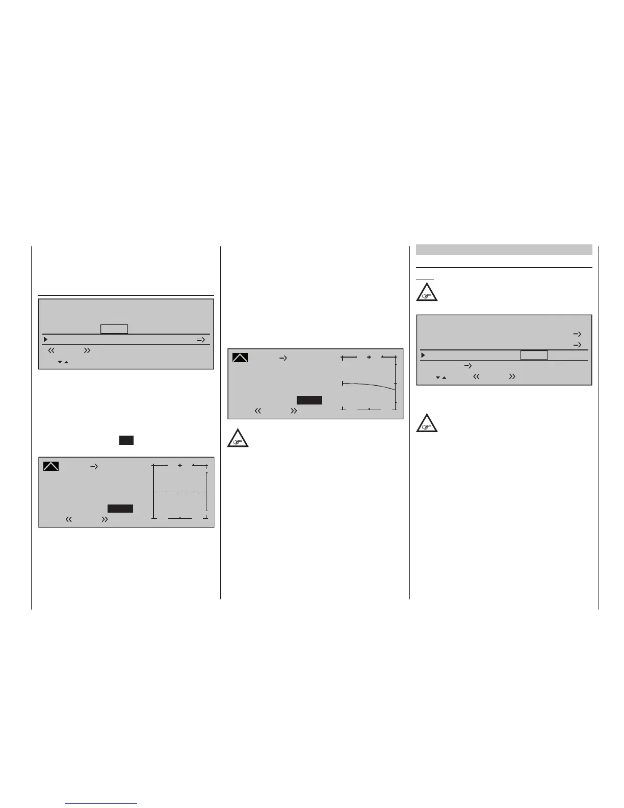
Elevat. curve (Brake Elevator)
Elevat. curve
BRAKE SETTINGS
Normal
Crow
AILE
0%
WK2
0%
FLAP
0%
Diff. reduct
FL2
0%
0%
0%
If the airbrake control – to be set to 1, 7, 8 or 9 on the
"Brake Offset" line of the »Model type« menu, page
95 – is used to extend the flaps as described previously
for the "Brake settings" menu, this will often have a
negative effect on the aircraft model's airspeed. This
mixer can be used to compensate this type of effect by
applying a corrective value to the elevator.
A brief tap on the centre SET key of the right touch
pad will switch to the display screen shown below:
Brake
Curve
off Point
Output
Input –100%
0%
L
+
–
100
O U T P U T
0%
Elevator
Normal
Setting notices for "Elevat. curve" (Brake
Elevator)
The offset set in the »Model type« menu, page 104,
affects this mixer.
The vertical line on the display that indicates the posi-
tion of the airbrake control only moves from the edge
of the graph when the configured offset is exceeded.
In doing so, airbrake control travel is automatically
expanded back to 100 %, as described in the »Model
type« menu.
Accordingly, the mixer's neutral point always lies on
the left edge, independently of the offset configured.
Now adjust the elevator curve in the direction of the
opposite end-point in accordance with requirements.
Note that this method for setting the 5-point curve
mixer follows the same principles that are applicable
to the curve mixers, already described on page 140 in
the context of the »Channel 1 curve« menu.
Brake
Curve
off Point
Output
Input +100%
–25%
H
+
–
100
O U T P U T
–25%
Elevator
Normal
The selected setting should certainly be tried
out in sufficient altitude and, if necessary,
readjusted. When doing this, be sure to pay
attention that the model does not slow down too
much while the brake system is extended! Otherwise,
you run the risk that, after the braking system is
retracted, e. g. to extend a landing approach that was
too short, for example, your model pancakes or even
stalls.
Display “Wing mixer”
Aileron differential
Note:
(Only for "2AIL 1FL". For the "2/4 AIL 2/4 FL"
selection, this is included on the Multi-flap
menu, see page 182.)
Aileron differential
Brake settings
0%
Aileron
0%
WING MIXERS
–––
rudder
2 4
Normal
Multi-flap menu
On this line you can set the aileron differential for the
two aileron servos.
If you are unsure about the meaning of differ-
ential travel, please read the appropriate
explanation at the start of this section on
page 174.
The setting range of -100 % to +150 % permits correct
differentiation direction adjustment regardless of the
direction of rotation of aileron and flap servos.
A simultaneous tap on the or keys of the
right touch pad (CLEAR) will reset a changed value
in a given active (inverse video) field back to 0 %.