211
Program description - Free mixers
Switching mixers in series
As already explained on page 208, you can also
switch mixers in series: Where mixers are switched
in "sequence", the "input signal" of a control channel
already on its way to the servo "branches off" and is
directed to a further channel. In the “type” column,
select the right angle bracket “
” or “Tr ”, if the trim
should also act simultaneously on the mixer input:
7
LinearMIX 1
type
6
from – Begr. +
8
7
??
??
??
??
??
??
––––
LinearMIX 2
LinearMIX 3
LinearMIX 4
LinearMIX 5
to
Adjust
Tr
––––
––––
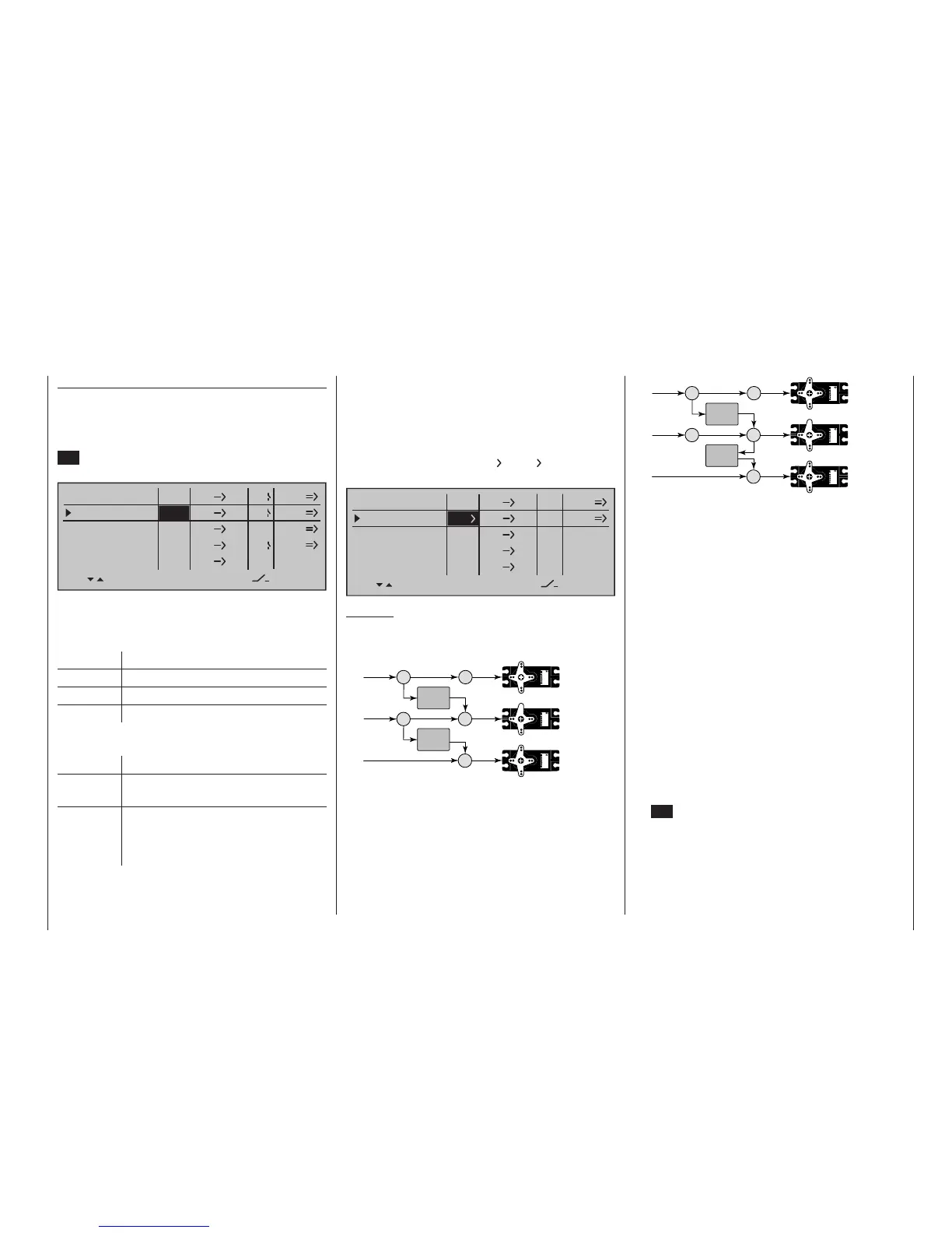
Example:
Two mixers (MIX 6 7 and 7 8):
a) WITHOUT series switching:
6 6
7
Servo
4,8 V
C 577
Best.-Nr. 4101
Servo
4,8 V
C 577
Best.-Nr. 4101
7
8
Servo
4,8 V
C 577
Best.-Nr. 4101
MIX 1
MIX 2
b) The same mixers WITH series switching:
6 6
7
Servo
4,8 V
C 577
Best.-Nr. 4101
Servo
4,8 V
C 577
Best.-Nr. 4101
7
8
Servo
4,8 V
C 577
Best.-Nr. 4101
MIX 1
MIX 2
In this highly simplified example, if mixer 2 is switched
in series, then it does not "take over" solely the trans-
mitter signal of control function 7 – as shown under
a) – but, instead, the entire (mixed) signal present at
the servo side of control channel 7, as shown under
b). It then directs this in accordance with its config-
ured mixer ratio forwards to control channel 8. In this
case, the effect of transmitter control "6" extends as
far as output "8". This kind of serial linkage can be
extended as far as you wish. For example, another
mixer “8 12” can be used to route the control signal
from “6” as far as output “12”, taking into considera-
tion the associated mixer ratios. Of course, even with
an active serial link, each separate mixer can still be
controlled via the transmitter control assigned to the
mixer input. Fixed-wing and helicopter mixers also
work in the same way, when set up to switch "in se-
quence".
Including phase trim
If you wish to apply the FLAP channel (“6”) or FLAP2
channel (“9”) trim values stored in the »Phase trim«
menu – flight phase dependent – then first tap the cen-
tre SET key of the right touch pad and use its selec-
tion keys to select "P":
"Type"
Including the trim
For control functions 1 … 4, you can also allow trim-
ming of the digital trim wheel for the given stick effect
the mixer's input. In this case, briefly tap the centre
SET key of the right touch pad then use the selection
keys to select “Tr” in the inverse video field:
EL
LinearMIX 1
type
6
from – Begr. +
EL
C1
8
3
EL
S
??
??
––––
LinearMIX 2
LinearMIX 3
LinearMIX 4
LinearMIX 5
to
Adjust
4
C4
2
Tr
off
off
off
The effect of the C1 trim wheel on mixer output will
depend on the function assigned in the »Model type«
menu (page 104), in the "Motor on C1" column for
fixed-wing models …
Trim Effect on mixer output
None linear over full trim wheel travel
Forward Only effective if C1 stick is forward
Back Only effective if C1 stick is back
… or on the "Pitch" line of the »Stick mode« menu
(page 116) for helicopter models:
Trim Effect on mixer output
AR
(Thr-AR)
linear over full trim wheel travel
TL
(throttle
limit)
only effective at minimum position of
the assigned throttle limit control (the
right side proportional rotary control as
standard)