253
Program description - Telemetry
… not only via an No. 7168.6A adapter cable to up-
grade the receiver but also connected to a telemetry
sensor.
However, in order for the receiver to correctly rec-
ognize the given connected device correctly, servo
connection 5 (in this case) MUST be appropriately set
for either "SERVO" or "SENSOR".
This switchover is accomplished by moving the
with the selection key of the left or right touch pad
until the "
" symbol is at the left margin of the bottom
line then tapping on the centre SET key of the right
touch pad.
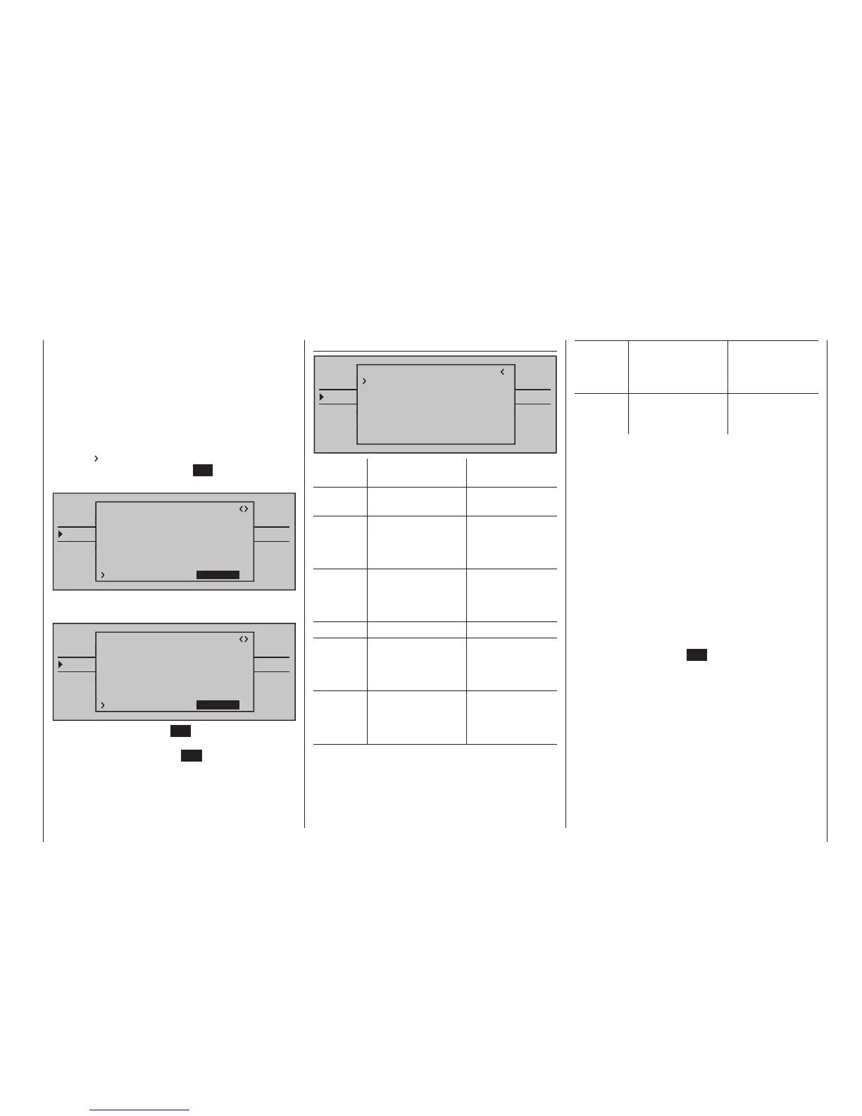
TELEMETRY
SETTING & DATAVIEW
SENSOR SELECT
RF STATUS VIEW
VOICE TRIGGER
TELEMETRI RCV
BIND. 1
RX CURVE V3.98
TYPE : A
CURVE1 CH : 02
TYPE : A
CURVE2 CH : 03
TYPE : B
CURVE3 CH : 04
5CH FUNCTION:SERVO
Now use one of the selection keys on the right
touch pad to select the alternative setting "SENSOR".
TELEMETRY
SETTING & DATAVIEW
SENSOR SELECT
RF STATUS VIEW
VOICE TRIGGER
TELEMETRI RCV
BIND. 1
RX CURVE V3.98
TYPE : A
CURVE1 CH : 02
TYPE : A
CURVE2 CH : 03
TYPE : B
CURVE3 CH : 04
5CH FUNCTION:SENSOR
Another tap on the centre SET key of the right touch
pad will close the selection and, with appropriate
repetitive taps on the centre ESC key of the left touch
pad, a return to the transmitter's basic display is ac-
complished.
RX SERVO TEST
TELEMETRY
SETTING & DATAVIEW
SENSOR SELECT
RF STATUS VIEW
VOICE TRIGGER
TELEMETRI RCV
BIND. 1
RX CURVE V3.98
ALL–MIN : 1000µsec
ALL–MAX : 2000µsec
ALARM VOLT : 3.8V
TEST : STOP
ALARM TEMP–:–10°C
ALARM TEMP+: 70°C
CH OUT TYPE:ONCE
Value Explanation
Possible
settings
Xx.xx Receiver’s firmware
version
None
ALL-MAX Servo travel on the
"+" side for all servo
outputs for the
servo test
1500 … 2000 µs
ALL-MIN Servo travel on the
"-" side for all servo
outputs for the
servo test
1500 … 1000 µs
TEST Test procedure START / STOP
ALARM
VOLT
Alarm threshold
of the receiver
undervoltage
warning
3.0 … 7.5 V
factory setting:
3.8 V
ALARM
TEMP+
Alarm threshold for
excessively high
temperature of the
receiver
50 … 80 °C
Factory setting:
55 °C
ALARM
TEMP–
Alarm threshold
for excessively low
temperature of the
receiver
-20 … +10 °C
Factory setting:
-10 °C
CH
OUTPUT
TYPE
Channel sequence ONCE, SAME,
SUMI, SUMO and
SUMD
ALL-MAX (servo travel on the "+" side)
In this line you set the maximum servo travel on the
plus side of the control travel for the servo test.
2000 µs corresponds to the full throw; 1500 µs corre-
sponds to the neutral position.
Make sure that the servos do not overrun mechani-
cally during the test routine.
ALL-MIN (servo travel on the "-" side)
You adjust the maximum servo travel on the minus
side of the control path for the servo test in this line.
1000 µs corresponds to the full throw; 1500 µs corre-
sponds to the neutral position.
TEST
You start and stop the servo test integrated in the
receivers in this line.
A brief tap on the centre SET key of the right touch
pad will open the entry field: