267Program description - Multichannel
Column 3, "Offset"
–––
Offset
Input 1
Input 2
Input 3
Input 4
fr
fr
fr
–––
–––
–––
+100%
+100%
+100%
+100%
+100%
+100%
+100%
+100%
0%
0%
0%
0%
– travel +
3
MULTICH 2
The control centre for the given control, i. e. its zero
point, can be changed in this column. The adjustment
range lies between -100 % and +100 %.
Simultaneously tapping on the or keys of the
right touch pad (CLEAR) will reset the value dis-
played in inverse video back to its "0 %" value.
Leave the offset setting at 0 % while making switch
assignments.
Column 3, "–travel+"
–––
offset
INPUT 1
INPUT 2
INPUT 3
INPUT 4
fr
fr
fr
–––
–––
–––
+100%
+100%
+100%
+100%
+100%
+100%
+100%
+100%
0%
0%
0%
0%
– travel +
3
MULTICH 2
Finally, transmitter control travel is set for both sides
in the rightmost column "-travel+". The range for this
lies between -100 % and +100 %. To accomplish this,
push or turn the respective transmitter control in the
given direction. This will set the "travel" for each given
direction individually.
If the assignment is for a switch, leave the setting at
the default value of 100 %.
M
6 (output: 5 ... 8)
5 (output 5 ... 8)
(Receiver power supply to the „B + -“
marked terminals)
Best.-Nr. 4159
Max. 8 x 0,7 A
Batt. 3...30V
NAUTIC - Expert
Schaltbaustein
2 - 16 K
Empfänger
1- H -2
1- G -2
1- F -2
1- E -2
1- D -2
1- C -2
1- A -2
1- B -2
Best.-Nr. 4142.N
1/4 K
NAUTIC
Multi-Prop-
Mini-Decoder
RX
S 4
S 3
S 2
S 1
external power-
supply 3 ... 30 V
- +
+
-
Current consumption of directly
connected consumer units
(but no electric motors)
max. 0,7 A (total max. 8 x 0,7 A).
Wiring for direct connection of two consumer units at one output
3-pole cable with flat connector Order No. 3941.6
red
brown
orange
consumer
unit
max. 0,7 A
consumer
unit
max. 0,7 A
additional modules e.g....
Switching module high voltage SXH Order No. 3970
Switching module multi function SXM Order No. 3971
Switching module
high voltage
SXH Order No. 3970
Switching
module
SXH
Switching
module
SXM
Switching module
multi function
SXM Order No. 3971
Soundswitch
Order No. 2382
Light module
Order No. 2381
7 (output: 5 ... 8)
8 (output: 5 ... 8)
additional servos, speed controller,
sail winch, ... also on this side
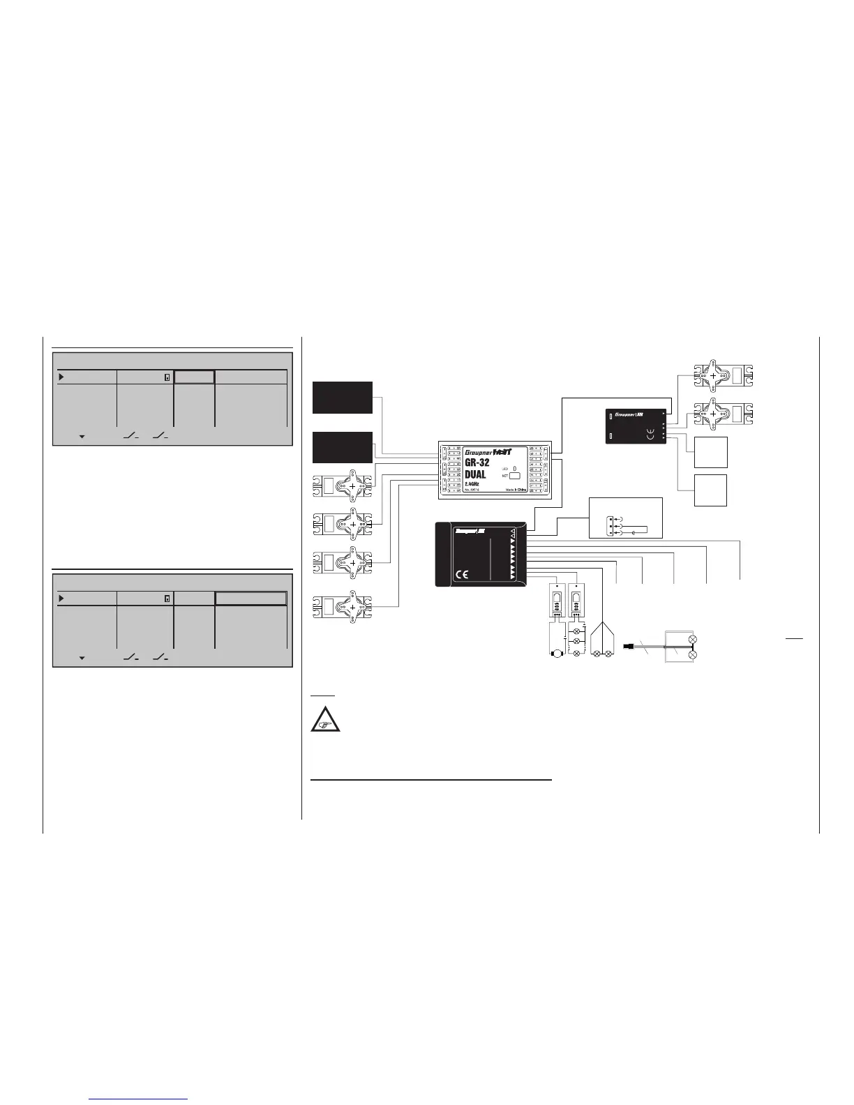
The figure shows an example of the connectivity of the ' 2-16 C NAUTIC
Expert Switch building block "," 1/4 K NAUTIC Multi-Prop Mini-Decoder ",
" light module "and" sound switch ". Two of these modules in parallel can
be operated using the menu »Multi channel« on output 5 ... 8.
Before first time operation of the NAUTIC modules make the above described settings.
Connection example with the Graupner HoTT GR-16 receiver
Note:
Due to technical reasons, servos connected
to a 1/4 C NAUTIC Multi-Prop mini decoder
may operate somewhat hesitatingly. This is
not a fault.
Connection notes for the
Nautic-Expert switching module, No. 4159
As many as 16 switched functions can be controlled
per switching module.
Eight loads, like lamps, LEDs, etc. – but not electric
motors – , with a load current of up to 0.7 A each can
be connected directly.
Two switch functions per connector socket are pos-
sible via the three conductor cable, No. 3941.6 , see
bottom right figure.
Electric motors and loads drawing substantial current
should be connected by other means, e. g. via switch-
ing modules. Ask your dealer about this.