297
Programming examples - Winged models
8
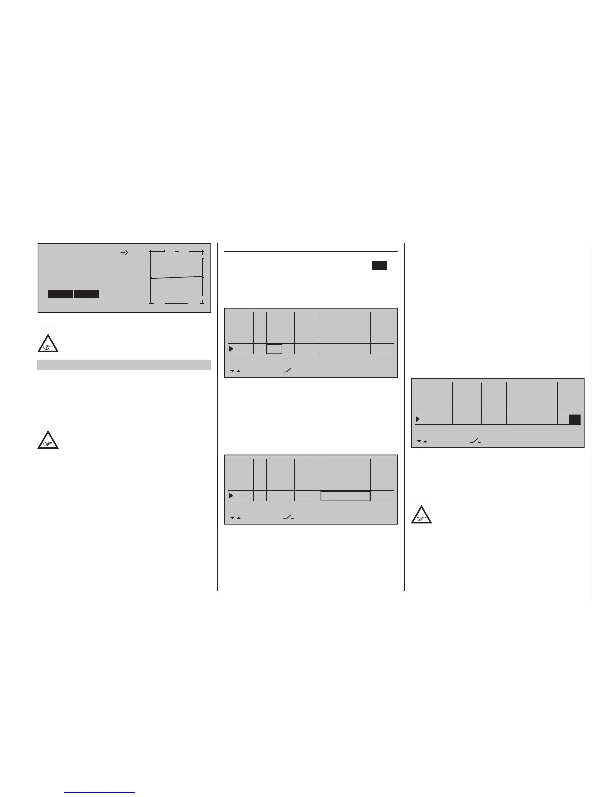
Mix input Offset
+
–
100
O U T P U T
0%
EL
Linear MIX 1
+4%
SYM ASY
SET
STO
+4%
Note:
The adjustment of a curve mixer is described
in detail in the section »Channel 1 curve«
starting on page 140.
Example 1
Proportional control usage
If one of these controls is used, the connection is very
simple. Only the motor controller (speed control) has
to be connected to a free servo connection 5 … 16 of
the receiver.
Bear in mind that, depending on the model
type and number of aileron and ap servos,
the output 2 + 5 or 6 + 7 are already linked.
Therefore connect your speed controller to the next
free input and assign the selected input – for exam-
ple, "Inp. 8" – to one of the transmitter's proportional
controls, for example the left-side proportional rotary
control. This is done in the menu …
A simultaneous tap on the keys of the left touch
pad now will switch over to the »Servo display«
where the selected proportional control can be acti-
vated to watch the bars for channel 8 "wander" from
one side to the other and back.
However, if the proportional control is moved too
fast – in practice – the resulting sudden motor ac-
celeration can briefly strain the entire drive train (too
much). In this case, be sure to enter a value in the "-
time +" column to counteract such a condition.
Therefore, using one of the selection keys, switch
one column to the right, to the "- time +" column then
move the selected control close to "full throttle" so the
marker frame is only placed around one value field.
Now enter a value of at least 1 s …
0%
+100%I5
I6
I7
I8
Ty p
SEL
+100%
0.0 0.0
– travel + –time+
0%
+100%
+100%
0.0 0.0
0%
+100%
+100%
0.0 0.0
0%
+100%
+100%
0.0
GL
GL
GL
fr ---
fr
fr
Cn2
---
---
---
offset
GL
Normal
1.0
… with which a movement of the proportional control
in the "ON" direction which is too fast is processes
move gently, and you can check immediately this by
switching to the »Servo display«.
Note:
No delay is entered on the "OFF" side, so
that the drive can be switched off instantly at
any time. This does not additionally stress the
drive, because it merely "runs down".
»Control adjust« (page 118)
Select the desired line with the selection keys of
the left or right touch pad. A tap on the centre SET
key of the right touch pad will activate the “Control
assignment”. Now move the selected proportional
control. After a short time, an entry, e. g. "Cn2", will
appear in the inverse video field.
0%
+100%I5
I6
I7
I8
Ty p
SEL
+100%
0.0 0.0
– travel + –time+
0%
+100%
+100%
0.0 0.0
0%
+100%
+100%
0.0 0.0
0%
+100%
+100%
0.0 0.0
GL
GL
GL
fr ---
fr
fr
Cn2
---
---
---
offset
GL
Normal
However, since propulsion must usually be available,
independent of the current flight phase, leave the
default value "GL" in the "Typ" column – as already
mentioned earlier in this section.
If applicable, for necessary adjustment of appropriate
control travel for the motor control (speed control),
use one of the arrow keys to switch to the right into
the "- travel +" column.
0%
+100%I5
I6
I7
I8
Ty p
SEL
+100%
0.0 0.0
– travel + –time+
0%
+100%
+100%
0.0 0.0
0%
+100%
+100%
0.0 0.0
0%
+100%
+100%
0.0 0.0
GL
GL
GL
fr ---
fr
fr
Cn2
---
---
---
offset
GL
Normal
This fields of this column can be use to set the travel
required, even asymmetric if necessary.