298
Programming examples - Winged models
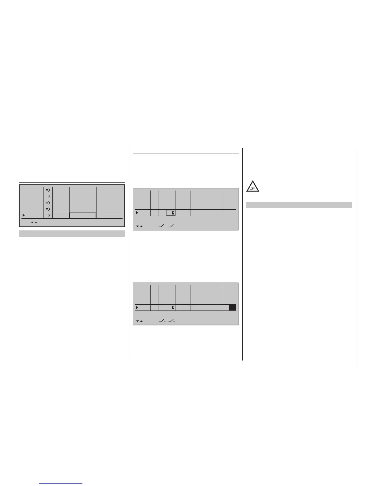
»Control adjust« (page 118)
… differ. As in example 1, change over to the line of
a free input, activate the "Switch and control assign-
ment" in the second column, page 60, then move the
selected switch, in this case for example switch 2,
from the desired motor OFF position in the direction
of motor ON.
0%
+100%I5
I6
I7
I8
Ty p
+100%
0.0 0.0
– travel + –time+
0%
+100%
+100%
0.0 0.0
0%
+100%
+100%
0.0 0.0
0%
+100%
+100%
0.0 0.0
GL
GL
GL
fr ---
fr
fr
---
---
offset
GL
Normal
2
---
Here again – as already mentioned earlier in this
section – leave the standard default "GL" in the "Typ"
column.
The setting of the appropriate control travel for the
motor control (speed control) is made in the "- trav-
el +" column. If the motor should up gently with the
use of a motor control (speed control), an appropriate
delay time can be set – as described in Example 1 – in
the "- time +" column:
0%
+100%I5
I6
I7
I8
Ty p
+100%
0.0 0.0
– travel + –time+
0%
+100%
+100%
0.0 0.0
0%
+100%
+100%
0.0 0.0
0%
+100%
+100%
0.0
GL
GL
GL
fr ---
fr
fr
---
---
offset
GL
Normal
2
---
1.1
All other settings – as already mentioned earlier in the
example – are made analogous to Example 1. There-
fore, the same comments and recommendations also
apply.
Note:
No delay is entered on the "OFF" side, so
that the drive can be switched off instantly at
any time. This does not additionally stress the
drive, because it merely "runs down".
Example 3
3-way switch usage
This variant realizes a three-stage speed setting,
such as Motor OFF, "half" and full power.
A corresponding motor control (speed control) is
required on the receiver side.
The required settings are basically the same as those
described under Example 1 and 2. Therefore, the
same comments and recommendations also apply.
Apart from the infinitely variable motor control under
Example 1 and the three-stage motor control in this
example, the selection of the operating element only
has an effect on the type of clock control, see page
284, and the nature of the assignment.
Here again – as already mentioned earlier in this
section – leave the standard default "GL" in the "Typ"
column.
Put the desired 3-way switch into its middle posi-
tion then activate the “Switch assignment” above the
column with the switch symbol, as described on page
56. Now put the selected 3-way switch forward, out of
its middle position:
The adjustment of the appropriate control travel and
directions for the motor control (speed control) is nor-
mally carried out in the »Control adjust« menu in the
"- travel +" column. Alternatively, these settings can
also be made in the menu …
»Servo adjustment« (page 112)
+100%
100%Servo 4
Servo 5
Servo 6
Servo 7
Servo 8
Rev cent.
100%
150% 150%
– travel + – limit +
+100%
100%
100%
150% 150%
+100%
100%
100%
150% 150%
+100%
100%
100%
150% 150%
+100%
100%
100%
150% 150%
Example 2
2-way switch usage
This variant realizes a purely ON/OFF function.
On the receiver side, either a simple electronic switch
or – if a gentle motor start-up, for example, is de-
sired – an appropriate motor control (speed control) is
required.
With the exception of assigning a different operating
element, the settings required for this are essen-
tially the same as those described under Example 1.
Therefore, the same comments and recommenda-
tions also apply.
Apart from the infinitely variable motor control under
Example 1 and the two-stage motor control in this
example, the selection of the two transmitter control
types only has an effect on the type of timer control,
see page 304.
Only the nature of the assignment and representation
of the selected switch in the display of the menu …