309
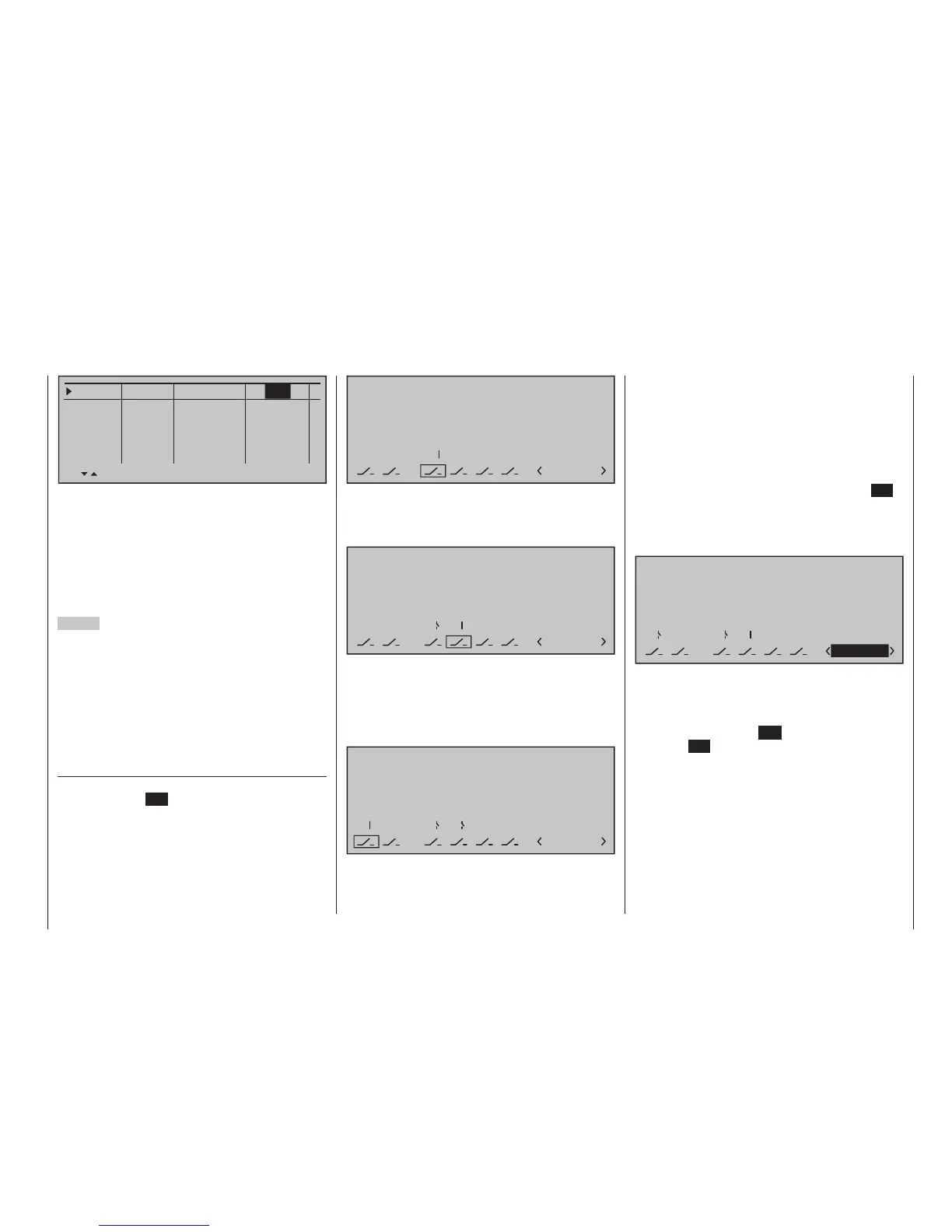
Programming examples - Using ight phases
Phase 1
Phase 2
Phase 3
Phase 4
Phase 5
1.0s
0.1s
0.1s
0.1s
0.1s
Name
Timer Sw.time
–
–
–
–
Normal
Thermal
Speed
Launch
… a "blend-in" time can be established for the time in
which a changeover from any other flight phase into
this given flight-phase is to be accomplished in order
to permit a "smooth" transition for different servo posi-
tions. Thus, an increased stress of the model under
certain circumstances with a "hard" change of rud-
der or flap positions, for example, is prevented. The
"Status" column shows you the currently active flight
phase with an asterisk "".
2
nd
Step
In order to actually be able to switch between the indi-
vidual flight phases, the assignment of one or multiple
switches is necessary. Either one of the two three-
way switches is ideally suited for switching between
up to three flight phases.
Each of the two switch end positions starting from the
centre position will be assigned to one of the flight
phase switches A … F. The assignment of the switch
takes place in the menu …
»Phase assignment« (page 160)
First select "C" with the marker frame. Then briefly
tap on the centre SET key of the right touch pad and
move the switch from its centre position to one of its
end-positions, for example, forward:
P H A S E ASSIGNMENT
Prior .
C
1 Normal
combi
A
B D E F
2 7
6
Move the switch back to the centre position and then
select "D", and after activation of the switch assign-
ment, move the switch to the other limit position, for
example, back:
P H A S E ASSIGNMENT
Prior .
C
1 Normal
combi
A
B D E F
2 7
6
7
Now the 3-way switch is programmed.
Now and additional switch could be assigned for the
"start" flight phase, if applicable. In this case under
"A", so that the "start" phase is always switched to
from every other flight phase in parallel to the switch-
ing-on of the motor:
P H A S E ASSIGNMENT
Prior .
C
1 Normal
combi
A
B D E F
2 7
6
7
2
The given switch positions must then be assigned
to respective flight phases (names). Although some
flight phases have already been assigned to names,
the phase name «1 Normal» will always initially ap-
pear at the right in the display; see the figures above.
First move the 3-way switch to one of its limit posi-
tions, for example to the top, and switch with the
marker frame in the display down to the right to set
the flight phase name. Briefly tap on the centre SET
key of the right touch pad to activate the entry field
then select the desired flight phase for this switch
position, in this example «2 Thermal», with the selec-
tion keys:
P H A S E ASSIGNMENT
Prior .
C
combi
A
B D E F
2 7
6
7
2
2 Thermal
Proceed in the same manner for the other switch limit
position, which is assigned the name "3 Speed".
If applicable move Switch 2 and assign this switch
combination the name "4 Start".
A brief tap on the centre ESC of the left touch pad or
the centre SET key of the right touch pad will com-
plete the phase name assignment.
The flight-phase dependent model settings made
before the assignment of phase switches are now in
the flight phase «1 Normal». This is the phase which
is called with the open «Start» switch in the centre
position of the 3-way switch.