314
Programming examples - Using ight phases
However, if flap positions are to be varied with
a switch or proportional control by the position
specified in the "FL-Pos." line, assign the desired
control to Input 6 in the »Control adjust« menu
and set the desired reaction to the movement of
the control selected for this purpose by way of
a percentage in this line.
• EL FL
This mixer induces a partial reaction from aileron
(AI) and camber flaps (FL) during elevator
activation.
The mixing direction is to be selected so that all
flaps are deflected downward with the elevator
pulled up and deflected upward with the elevator
pushed down (= hydroplane). The mix proportion
is normally in the low double-digit range.
• EL FL Off.
In the “EL FL” line you may have entered a
value to amplify the effect of elevator commands
in tight turns and aerobatics. In this “EL FL
offset” line you can enter an Offset value which
determines the “onset point” of the flaps when
elevator is applied:
• If you leave the Offset value at 0 %, the flaps
follow the travel of the elevator from the neutral
point of the elevator stick, at the percentage
rate set in the “EL FL” line.
• If you set an Offset value other than 0 %, the
flaps only follow the travel of the elevator in
the “down” and “up” direction after the eleva-
tor command has reached the selected Offset
point.
Now, within the »Wing mixers« menu, switch to the
"Brake settings" …
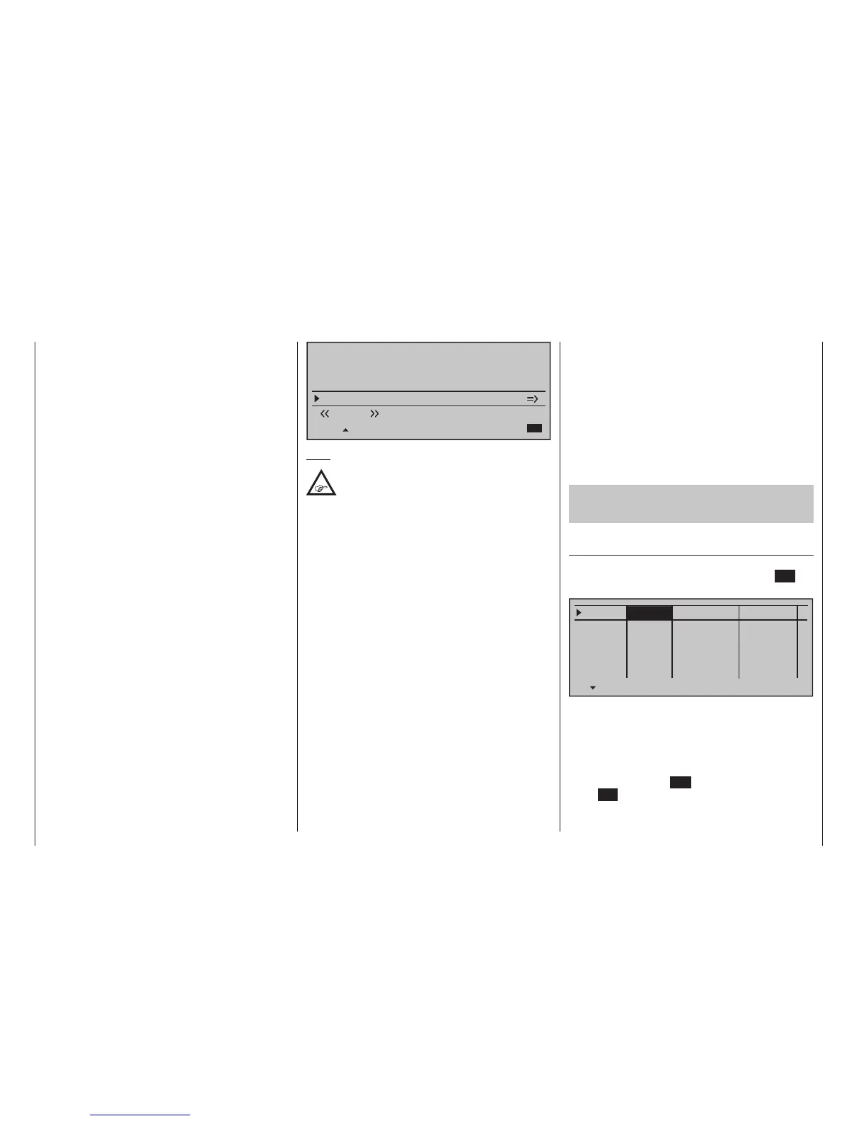
Elevat. curve
BRAKE SETTINGS
Normal
Crow
AI
+22%
WK2
0%
FL
+66%
Diff. reduct.
WK2
+33%
0%
+33%
Note:
The "Brake settings" menu is switched "off" if:
"Motor on C1 forward / back" in the »Model
type« menu (page 104) AND the "Motor"
column of the »Phase settings« menu, (page 154)
are set to "yes" for the currently active ight phase.
Change the ight phase, if applicable.
• Crow
Further above in this text section, the C1 stick was
set for brake system steering.
In this line you determine the share with which
the AI and FL should be included on actuation of
C1 in the manner that both ailerons are deflected
"slightly" upward and both flaps are deflected as
far downward as possible.
Now with a simultaneous tap on the keys
of the left touch pad, a change to the »Servo
display« menu can be affected for observation of
servo movements and, in particular, to ensure that
no influence on the flaps takes place above the
adjusted brake offset, e. g. +90 % and beyond to
the throw limit of the C1 control ("Idle travel" of the
C1 stick).
• Diff. reduct.
The value previously entered into the aileron
differentiation line should also be entered in this
"Differentiation reduction" line to fade this out
during braking.
• Elevat. curve
This line is used for the entry of any correction
factor that may be required for the elevator, see
page 187.
Insofar as necessary, again check all flap throws and,
by way of the »Servo adjustment« menu (page 112),
adjust the servo centre, the servo travel and the travel
limit.
It may also be time to start the initial flight testing,
insofar as all global settings – that is to say, all flight-
phase independent settings – are completed.
Two additional ight phases are now to be set up
below, each of which requires a somewhat differ-
ent ap position.
Therefore, switch to the menu …
»Phase settings« (page 154)
… and activate the assignment of phase names in the
"Name" column with a brief tap on the centre SET key
of the right touch pad:
Phase 1
Phase 2
Phase 3
Phase 4
Phase 5
0.1s
0.1s
0.1s
0.1s
0.1s
Name
Fl.ph.Tim. Sw. time
–
–
–
–
Now give Phase 1 – the "Normal phase" – that is also
the phase which includes the previous settings, the
name "Normal", which you select from a list with the
selection keys.
Phase 2 is given the name "Thermal" and Phase 3 is
given the name "Speed". Now conclude the entries
with a brief tap on the ESC key of the left touch pad
or the SET key of the right touch pad: