316
Programming examples - Using ight phases
»Copy / Erase« (page 74)
… and switch to the "Copy flight phase" line:
Copy flight phase
Erase model
Copy model –> model
Export to SD
Import from SD
=>
All eight possible flight phases are listed in "Copy
from phase":
Select the flight phase to be copied, e. g. "1 Normal".
7
Copy from phase:
3
5
=>
=>
2
4
6
1
8
Normal Thermal
Speed
With a brief tap on the centre SET key of the right
touch pad, switch the window to entry of the target
memory "Copy to phase".
Select phase "2 Thermal" as the target:
7
Copy to phase:
3
5
=>
=>
4
6
1
8
Normal
Speed
Thermal
2
Confirm the selection with a brief tap on the centre
SET key of the right touch pad.
A security query follows, who should be confirmed
with "Yes":
Phase to:
to be copied?
NO
1 Normal
2 Thermal
YES
Then repeat the process with flight phase "3 Speed".
Now we will program the required settings in the
ight phase "Thermal" as an example.
In order to vary camber flap positions in the «Ther-
mal» phase, it is merely necessary to switch over to
the menu …
»Control adjust« (page 118)
… then change Input 6 – as described beginning on
page 118 – from "GL(obal)" to "PH(ase)" and finally
assign it to an operating element.
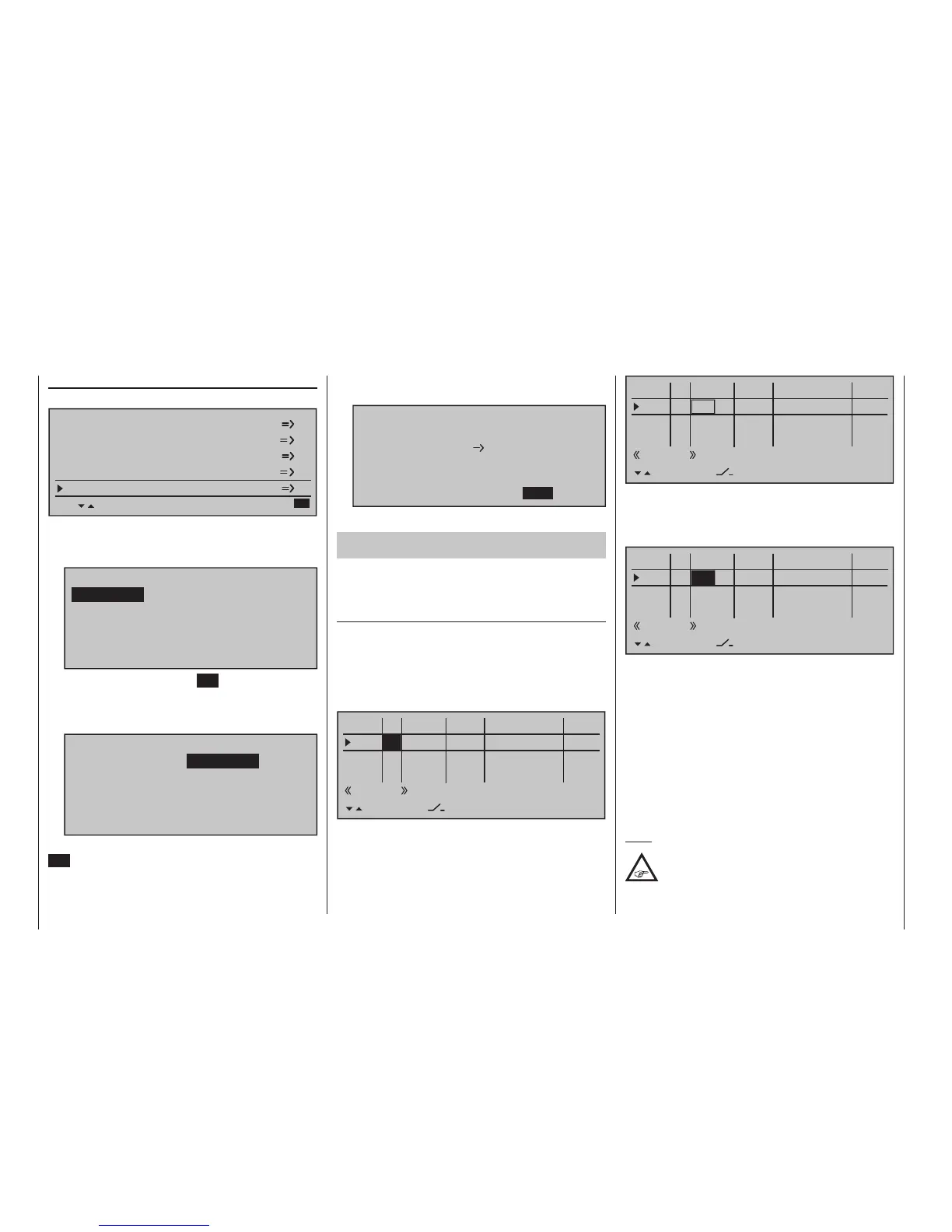
To do this, first use the selection keys to switch into
the "Typ" column for "I6" and change this setting from
"GL" to "PH".
0%
+100%I5
I6
I7
I8
Ty p
+100%
0.0 0.0
– travel + –time+
0%
+100%
+100%
0.0 0.0
0%
+100%
+100%
0.0 0.0
0%
+100%
+100%
0.0 0.0
GL
GL
fr
Cn1
fr
---
---
---
offset
GL fr
Thermal
PH
---
SEL
Thereafter change one column to the right into the
column above SEL …
0%
+100%I5
I6
I7
I8
Ty p
+100%
0.0 0.0
– travel + –time+
0%
+100%
+100%
0.0 0.0
0%
+100%
+100%
0.0 0.0
0%
+100%
+100%
0.0 0.0
GL
GL
fr
Cn1
fr
---
---
---
offset
GL fr
PH
---
SEL
Thermik
… and now assign this input, as described in the
section "Assigning transmitter controls, switches and
control switches" on page 60, the left proportional
slider in the middle console to, for example:
0%
+100%I5
I6
I7
I8
Ty p
+100%
0.0 0.0
– travel + –time+
0%
+100%
+100%
0.0 0.0
0%
+100%
+100%
0.0 0.0
0%
+100%
+100%
0.0 0.0
GL
GL
Cn1
fr
---
---
---
offset
GL fr
PH
---
SEL
Sl1
Thermal
This control will allow the ailerons (2 + 5) and camber
flaps (6 + 7) to be continuously adjusted (as camber
flaps) with a mixer ratio yet to be set via the »Wing
mixers« menu.
If you assign the still free second three-stage switch
to Input 6 instead, you can call three different FL posi-
tions of the ailerons (AIL) and camber changing flaps
(FL) as well as three elevator positions (Elev) in the
"Thermal" flight phase, see the following page. (These
three switch positions correspond to the centre posi-
tion and the two limit positions of the previously men-
tioned proportional rotary control.)
Note:
The FL and AIL ap positions in the two limit
switch positions or in the switch centre
depend on the value set in the column "-