97
Program description - Base setup models | Helicopter models
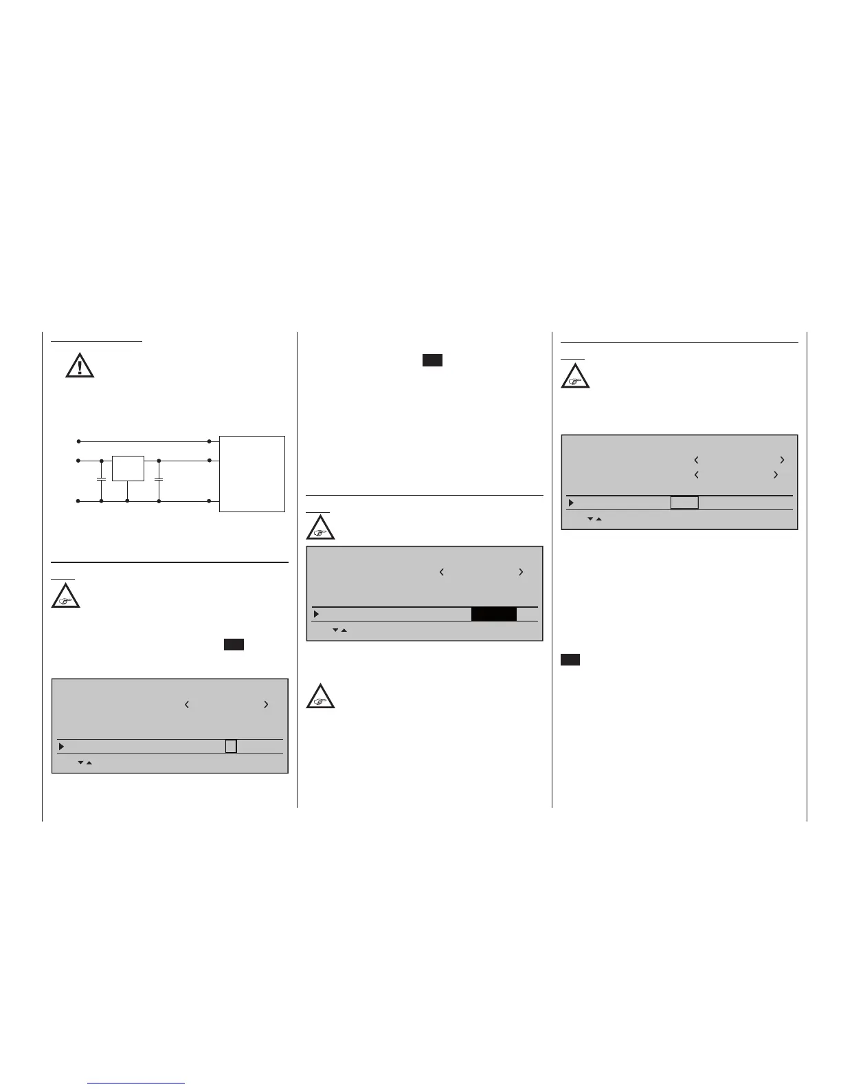
Important notes:
•
The output voltage of the DATA
socket is around 5 V, and must be
reduced to the power supply
voltage generally required by external
digital RF modules (3 to max. 3.3 V). This
is accomplished using the circuit which
is shown here in diagrammatic form:
GND
Vcc IN = 5 V
DATA +
DATA S
125000 baud signal
Vcc
GND
DATA -
22µF/6.3 V
22µF/6.3 V
Vcc OUT = 3 ... 3.3 V
Low Drop
Voltage
Regulator
SP.-MODULE
with
digital input signal
• Servo travels must be limited to max.
128 %.
SP channels
Note:
This menu line is suppressed in the “Module”
line if you select “HoTT” or “EXT.”.
If necessary, use the Select buttons of the left or
right-hand four-way button to move to the “SP chan-
nels” line, then briefly press the central SET button of
the right-hand four-way button to activate the Value
window:
Stick mode
1
BASIC SETTING,MODEL
Info
Module
1234g/111111
SEL
bind
1
SP module
SP channels
6
You can now select “6” or “8” channels using the right-
hand Select buttons. The procedure is concluded by
again pressing the central SET button of the right-
hand four-way button.
At the transmitter this selection only affects the num-
ber of control channels transferred to the external RF
module via the DATA socket. If you choose “6”, then
these are control channels 1 … 6; if you choose “8”,
these are channels 1 … 8.
Simultaneously pressing the or buttons of
the right-hand four-way button (CLEAR) returns the
display to “6”.
ext. PPM signal
Note:
This menu bar is hidden when “hott” in the
line “module”.
Stick mode
1
BASIC SETTING,MODEL
Info
Module
1234g/111111
SEL
PPM10
EXT. PPM
ext. PPM Signal
normal
Some RF modules which can be connected to the
external (page 27) or internal, page 29, connectors
for other RF modules require an inverted input signal.
Observe, however, the installation
instructions of the relevant module.
The choice of “inverted” instead of the default preset
“normal” allows for appropriate adaptation of the pro-
vided PPM signal.
A simultaneous tap on the or keys of the
right touch pad (CLEAR) will reset the display to
“normal”.
Receiver channel mapping
Note:
This menu line is when “EXT. PPM“ or ”SP
mode“ in the line ”module“ hidden.
As long as there is at least one “bound” HoTT receiv-
er in the “Module” line, the next line down will be the
“Rcv Ch map” line.
Model name
Stick mode
1
BASIC SETTING,MODEL
Info
Graubele
1234g/111111
SET SET SET SET
Rcv Ch map R16 R08
n/a
n/a
As mentioned in the introduction to the “Binding receiv-
ers” section, this menu item of the mc-32 HoTT
offers both the opportunity to freely divide up the trans-
mitter’s control channels within a receiver as well as
the opportunity to distribute the transmitter’s 16 control
channels across as many as four receivers. This re-
distribution is subsequently referred to as “mapping”
or “channel mapping” (channel correlation). Select the
receiver to be “mapped” with the selection keys of the
left or right touch pad then tap briefly on the centre
SET key of the right touch pad.
Channel mapping within a receiver
Analogous to the channel correlation function in
the »Telemetry« menu on page 249, described as
“Channel Mapping”, it is very simple to use this menu
item to freely assign the transmitter’s control channels
present on the receiver’s inputs to any specific receiv-
er outputs (servo connections) for the bound receiver
designated by the column labelled BD1.