90 IconMaster Installation and Configuration Manual
Chapter 4: Router Connections
3. On the second NSM back module, connect a maximum of 7 video audio
inputs to the BNC connections labeled In 1 to In 7.
4. Connect Out 1 on the first NSM to AES Bus A on the MKA-3901. This can
be done by direct connection, or by ICONM-BO-VAB or
ICONM-BO-VAC breakout module connection.
5. Connect Out 2 on the first NSM to AES Bus B on the MKA-3901.
6. Connect Out 1 on the second NSM to In 6 on the first NSM.
7. Connect Out 2 on the second NSM to In 7 on the first NSM.
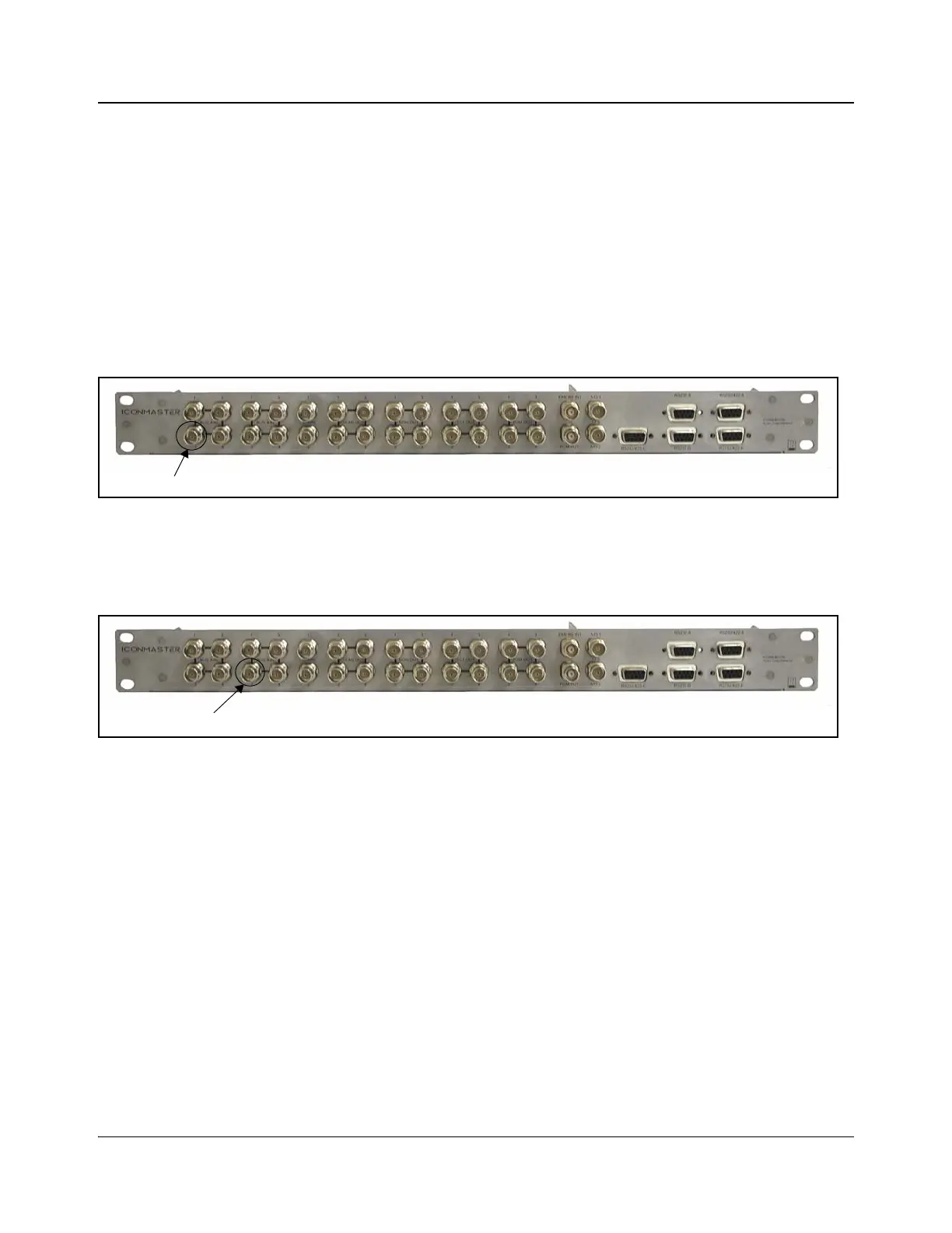
Audio output 1 from the third NSM router must be connected to Bus A In 2 on
the breakout module as shown in Figure 4-9.
Figure 4-9. Audio Output 1 From Third NSM Router to Bus A In 2
Audio output 2 from the third NSM router must be connected to Bus B In 2 on
the breakout module, as indicated in Figure 4-10.
Figure 4-10. Audio Output 2 From Third NSM Router to Bus B In 2
When using the IOCON-BO-VAB breakout module, audio output 1 from the
third NSM router must be connected to Input Bus A2 on the breakout module,
as indicated in Table 2-9 on page 54.
Audio output 2 from the third NSM must be connected to Input Bus B2 on the
breakout module, as indicated in Table 2-9 on page 54.