IconMaster Installation and Configuration Manual 113
Chapter 4: Router Connections
Audio output 1 from the level 2 Panacea router must be connected to Bus A In
2 on the breakout module, as indicated in Figure 4-26.
Figure 4-26. Audio 1, Level 2 Panacea Connection to ICONM-BO-VAC
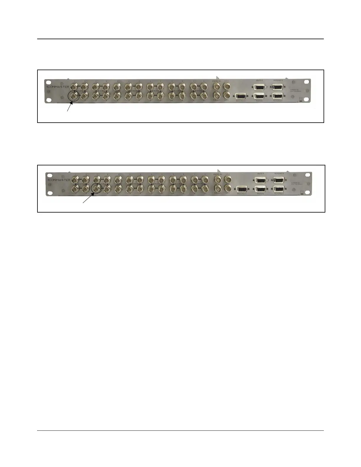
Audio output 1 from the level 2 Panacea router must be connected to Bus B In 2
on the breakout module, as indicated in Figure 4-27.
Figure 4-27. Audio 2, Level 2 Panacea Connection to ICONM-BO-VAC
Audio outputs 3 and 4 from the Panacea level 3 and 4 routers connect to Bus A
and B In 3 and 4, respectively.
When using the ICON-BO-VAB breakout module and a Panacea router (single
level), audio output 1 from the Panacea router must be connected to Input Bus
A1 on the breakout module as indicated in Table 2-9 on page 54.
Likewise, audio output 2 from the Panacea router must be connected to Input
Bus B1 on the breakout module as indicated in Table 2-9 on page 54.
Audio output 1 from the level 2 Panacea router must be connected to Input Bus
A2 on the breakout module as indicated in Table 2-9 on page 54.
Audio output 2 from the level 2 Panacea router must be connected to Input Bus
B2 on the breakout module as indicated in Table 2-9 on page 54.
Audio outputs 3 and 4 from the Panacea level 3 and 4 routers connect to Input
Bus A and B, 3 and 4, respectively.
3. Make Connections on the Panacea and MKE-3901
1. On the Panacea back module, connect a maximum of 16 video inputs to the
BNC connections labeled Input 1 to Input 16.
2. Connect Output 1 on the Panacea to Input Bus A on the MKE-3901.
3. Connect Output 2 on the Panacea to Input Bus B on the MKE-3901.
4. Connect your station reference to the Sync connection of the Panacea back
module.
5. Terminate one of the XY BNC connectors on the Panacea router.