IconMaster Installation and Configuration Manual 9
Chapter 2: Installation
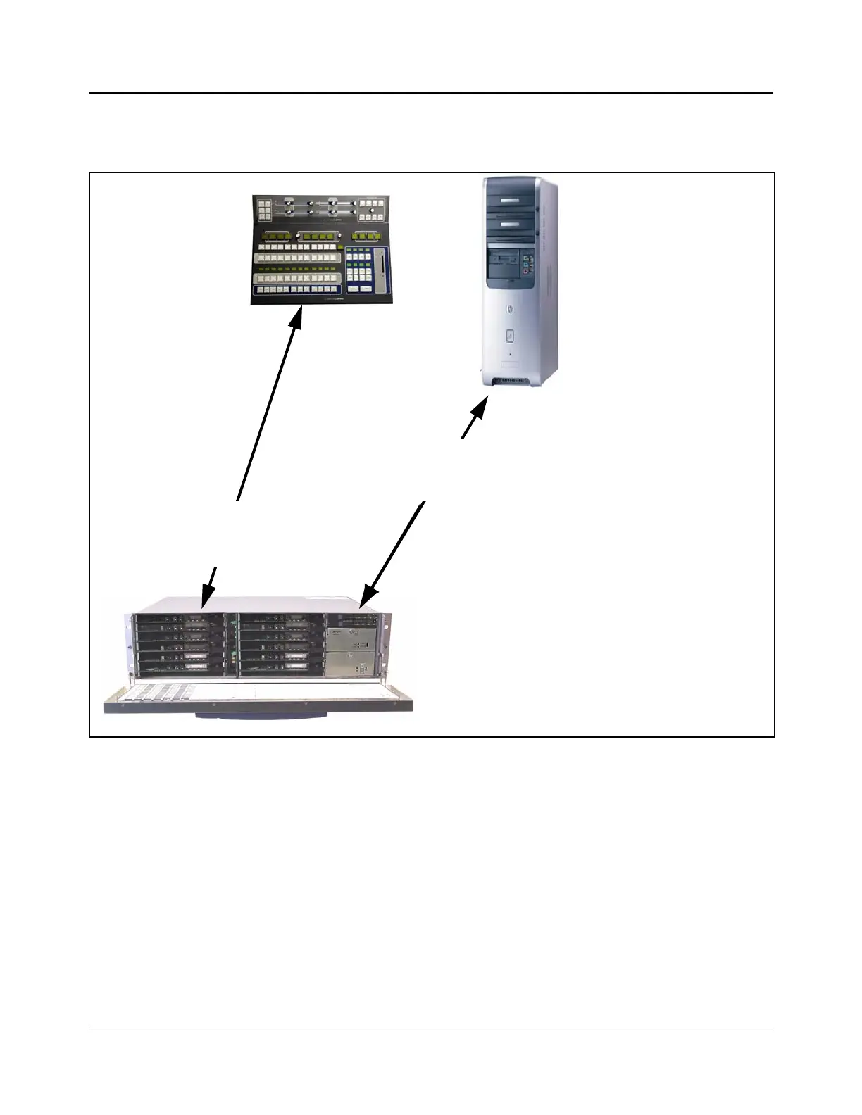
Figure 2-1 shows how an IconMaster system setup works. Each installation
component of this setup (except for the customer-supplied PC) is explained in
more detail in sequent sections.
Figure 2-1. IconMaster Components
Audio control panel
(optional)
Main control panel
FR-3923 NEO frame with redundant power supply
Modules are installed on one side in the
following order:
1. MKA-3901 (optional)
2. MKE-3901 (with optional “FX” submodule)
3. MGI-3903
Modules must be connected to one another before
installation
Customer-supplied PC
running IconMaster
configuration utility software
on Windows® 2000 or
Windows® XP
MKE-3901 to/from control panel on
Ethernet (directly or via switch; switch
must be 10Base-T or 10/100Base-T—not
100Base-T)
To/from MGI-3903 IconLogo SoftPanel, and
IconMaster configuration utility software
via switch