IconMaster Installation and Configuration Manual 41
Chapter 2: Installation
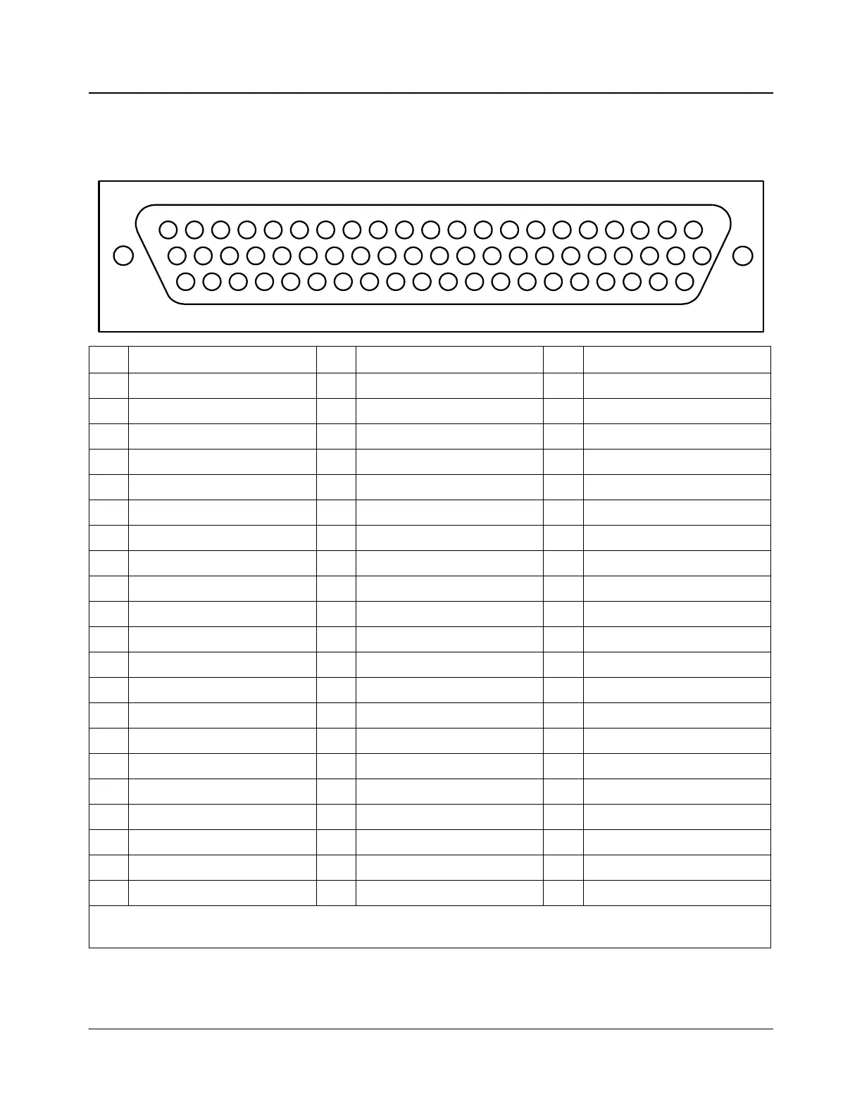
Table 2-3. MKA-3901 AES Input Connector Pinouts
This information is for use when it is necessary to wire directly to the AES input connector. If you are using a
ICONM-BO-VAC or ICONM-BO-VAB breakout module, this information is not required.
Pin Function Pin Function Pin Function
1 Spare 22 Ground 43 AES BUS A 4 (B-)
2 Spare 23 N/C 44 AES BUS A 4 (B+)
3 Ground 24 Ground 45 Ground
4 Spare 25 Ground 46 AES BUS A 2 (B-)
5 Spare 26 Ground 47 AES BUS A 2 (B+)
6 Ground 27 Ground 48 Ground
7 AES BUS A 3 (B+) 28 Ground 49 AES BUS B 4 (B-)
8 AES BUS A 3 (B-) 29 Ground 50 AES BUS B 4 (B+)
9 Ground 30 Ground 51 Ground
10 AES BUS A 1 (B-) 31 Ground 52 AES BUS B 2 (B-)
11 AES BUS A 1 (B+) 32 Ground 53 AES BUS B 2 (B+)
12 Ground 33 Ground 54 Ground
13 AES BUS B 3 (B-) 34 Ground 55 Reserved for future use
14 AES BUS B 3 (B+) 35 Ground 56 Reserved for future use
15 Ground 36 Ground 57 Ground
16 AES BUS B 1 (B-) 37 Ground 58 Reserved for future use
17 AES BUS B 1 (B+) 38 Ground 59 Reserved for future use
18 Ground 39 Ground 60 Ground
19 Reserved for future use 40 Ground 61 Reserved for future use
20 Reserved for future use 41 Ground 62 Reserved for future use
21 Ground 42 Ground
For balanced data, use B+ and B-. For unbalanced (coax), use B+ for the signal and connect B- to ground (shield). To
use the coax, the C version of the card must be purchased.
42
21
62
20
41
61
19
40
60
18
39
59
17
38
58
16
37
57
36
15
56
14
35
55
13
34
54
12
33
53
11
32
52
10
31
51
30
9
50
8
29
49
7
28
48
6
27
47
5
26
46
4
25
45
24
3
44
2
23
43
1
22