Appx.25
Terminology
Frequency 10 s
(Freq10s)
The frequency measured value as calculated according to IEC61000-4-30. This value
is an average of the frequencies measured for 10 s. It is recommended to measure this
characteristic for at least one week.
Harmonics A phenomenon caused by distortions in the voltage and current waveforms that affect
many devices with power supplies using semiconductor control devices. In the analysis of
non-sine waves, the term refers to one RMS value among the components with harmonic
frequencies
Harmonic content
percentage
The ratio of the K-th order size to the size of the fundamental wave, expressed as a
percentage using the following equation:
(K-th order wave) / (fundamental wave) × 100 [%]
By observing this value, it is possible to ascertain the harmonic component content
for individual orders. This metric provides a useful way to track the harmonic content
percentage when monitoring a specic order.
Harmonics phase
angle and phase
difference
The harmonic voltage phase angle and harmonic current phase angle are expressed in
terms of the synchronized source’s fundamental component phase.
The difference between each order’s harmonic component phase and the fundamental
component phase is expressed as an angle (°), and its sign indicates either a lagging
phase (LAG) “−” (negative) or leading phase (LEAD) “+” (positive). Angle signs of the
above are the opposite of those for power factor.
The harmonic voltage-current phase angle expresses the difference between each order’s
harmonic voltage component phase angle and harmonic current component phase angle
for each channel as an angle (°).
When using the sum display, the sum of each order’s harmonic power factor (calculated
from the sums of harmonic power and harmonic reactive power) is converted to an
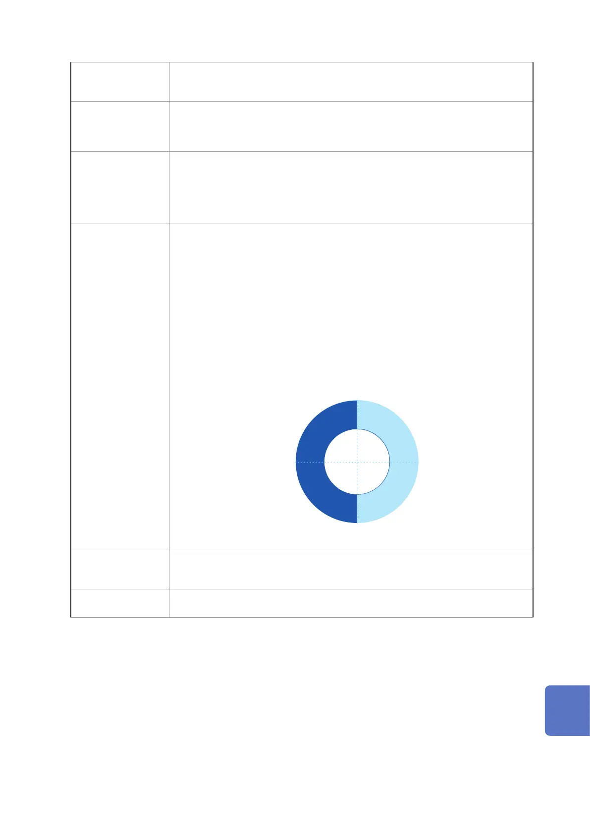
angle (°). When the harmonic voltage-current phase angle is between −90° and +90°,
that order’s harmonics are owing toward the load (inux). When the harmonic voltage-
current phase angle is between +90° and +180° or between −90° and −180°, that order’s
harmonics are owing from the load (outow).
−90°
90°
0°±180°
Voltage and
current phase
angles
Voltage and
current phase difference
LEAD
LAG
Harmonics phase angle
Inow
Outow
IEC61000-4-7 An international standard governing measurement of harmonic current and harmonic
voltage in power supply systems as well as harmonic current emitted by equipment. The
standard species the performance of a standard instrument.
IEC61000-4-15 A standard that denes testing techniques for voltage uctuation and icker measurement
as well as associated measuring instrument requirements.
10
9
8
7
6
5
4
3
2
1
Appx. Ind.

 Loading...


