86
Verifying the Voltage Details
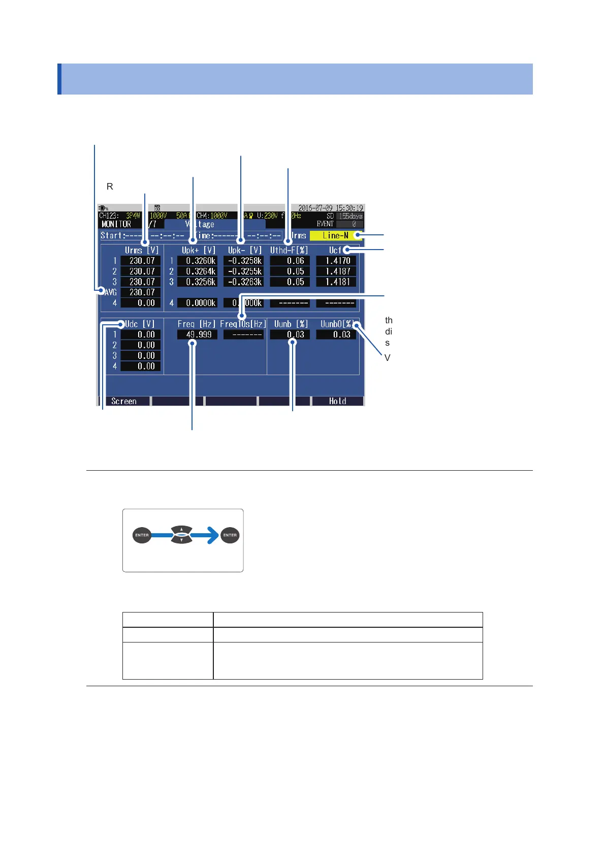
6.4 Verifying the Voltage Details
Press the [MONITOR] key to display the MONITOR, Voltage screen.
Frequency for 200 ms (average
value for a period of 200 ms)
Voltage DC value
Voltage waveform peak (+)
1
RMS voltage
Average value of the channels
Voltage waveform peak (-)
Voltage crest factor
([absolute value of voltage
waveform peak]/[RMS voltage])
Voltage zero-phase unbalance
factor (not displayed for 3-phase
3-wire line)
See “Unbalance factor” (p. Appx.29).
Voltage negative-phase unbalance factor
See “Unbalance factor” (p. Appx.29).
Frequency for 10 sec (average
value for a period of 10 s)
Displayed in red if one of
the following occurs: swell,
dip, interruption, or out of
synchronization.
Voltage total harmonic distortion
(calculation method THD-F / THD-R)
See Calculation method (p. 66).
1
When the wiring method is 3P3W3M, 3P4W, or 3P4W2.5E (available after the rmware update), the
display method of the RMS voltage can be switched (between phase voltage and line voltage).
Select
Phase voltage (Line-N), Line voltage (Line-Line)
For 1P2W, 1P3W Fixed to phase voltage
For 3P3W2M Fixed to line voltage
For 3P3W3M, 3P4W,
3P4W2.5E
Can be switched between the line voltage and phase voltage.
Both the phase voltage and line voltage are stored as a output
data. (3P4W2.5E is available after the rmware update)

 Loading...


