21
Names and Functions of Parts
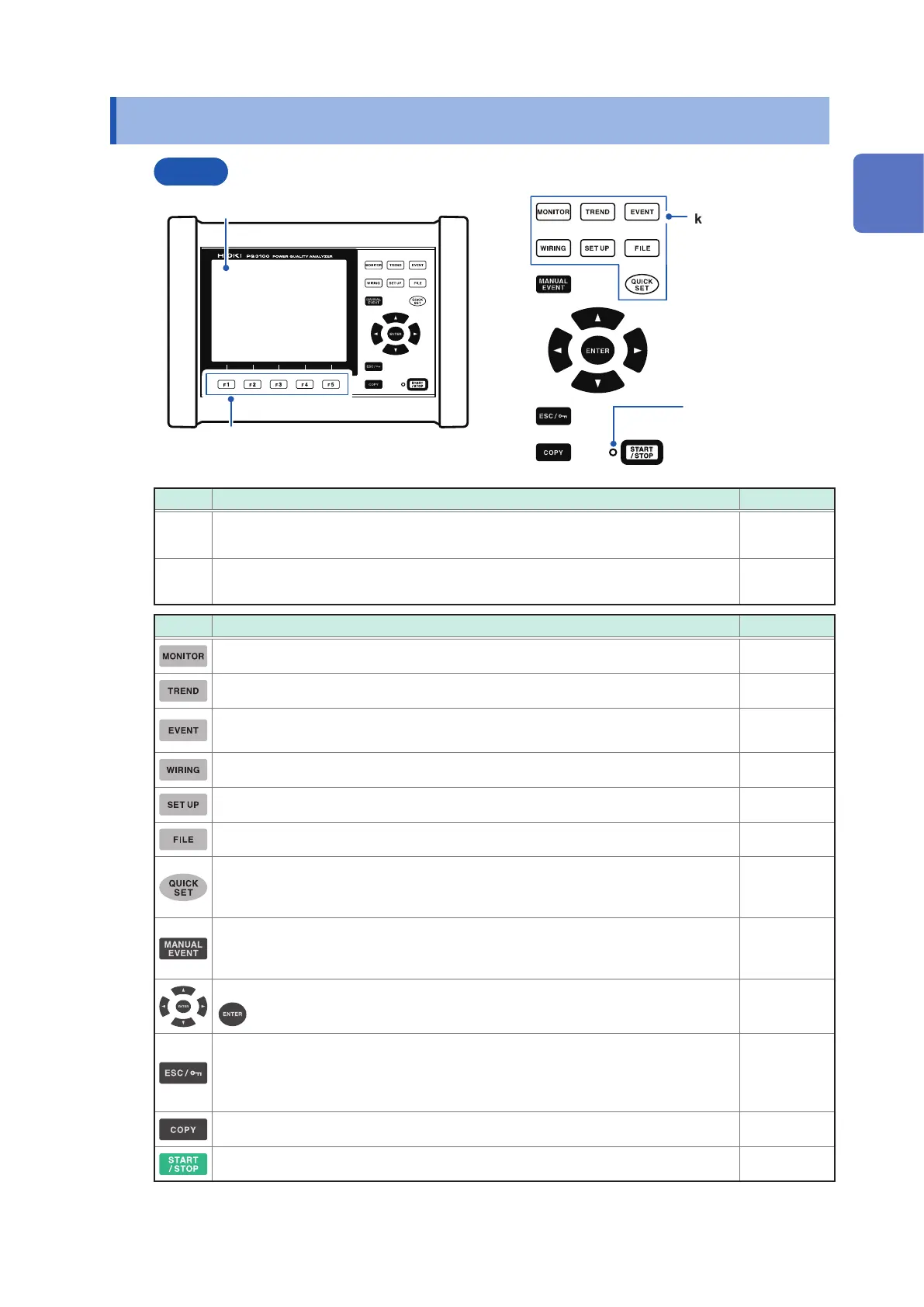
1.4 Names and Functions of Parts
Front
Operation keys
1
2
START/STOP LED
Flashing green: When
in the recording
standby state
Solid green: When
recording
Screen switching
key
No. Name and description Reference
1
Display
6.5″ TFT color LCD
p. 24
2
Function key ([F1] to [F5] key)
Select and change display contents and settings.
—
Keys Description Reference
Displays and changes the MONITOR screen (waveform and measured values). p. 81
Displays and changes the TREND screen (time series trend graphs). p. 95
Displays and changes the EVENT screen (event status).
(Version upgrade supported for switching)
p. 105
Displays and changes the WIRING screen (wiring settings, wiring check). p. 47
Displays and changes the SET UP screen (settings). p. 63
Displays and changes the FILE screen (SD memory card/internal memory). p. 115
Displays and changes the QUICK SET screen.
Pressing this key during recording allows checking the current main settings.
p. 45
Measure-
ment Guide
An event occurs at the timing when this key is pressed during recording.
The voltage and current waveforms and measured values when an event occurs
are recorded.
—
Moves the cursor on the screen. Scrolls through graphs or waveforms.
: Selects items on the screen and accepts changes.
—
Cancels any selections or changes made and reverts to the previous settings.
Switches to the previous screen.
Pressing and holding this key for at least 3 s activates the key lock function. (Same
operation for unlock)
—
Outputs the image of the currently displayed screen to the SD memory card. p. 121
Starts and stops recording. p. 91
1
Overview

 Loading...


