50
Wiring Method and Declared Input Voltage Settings
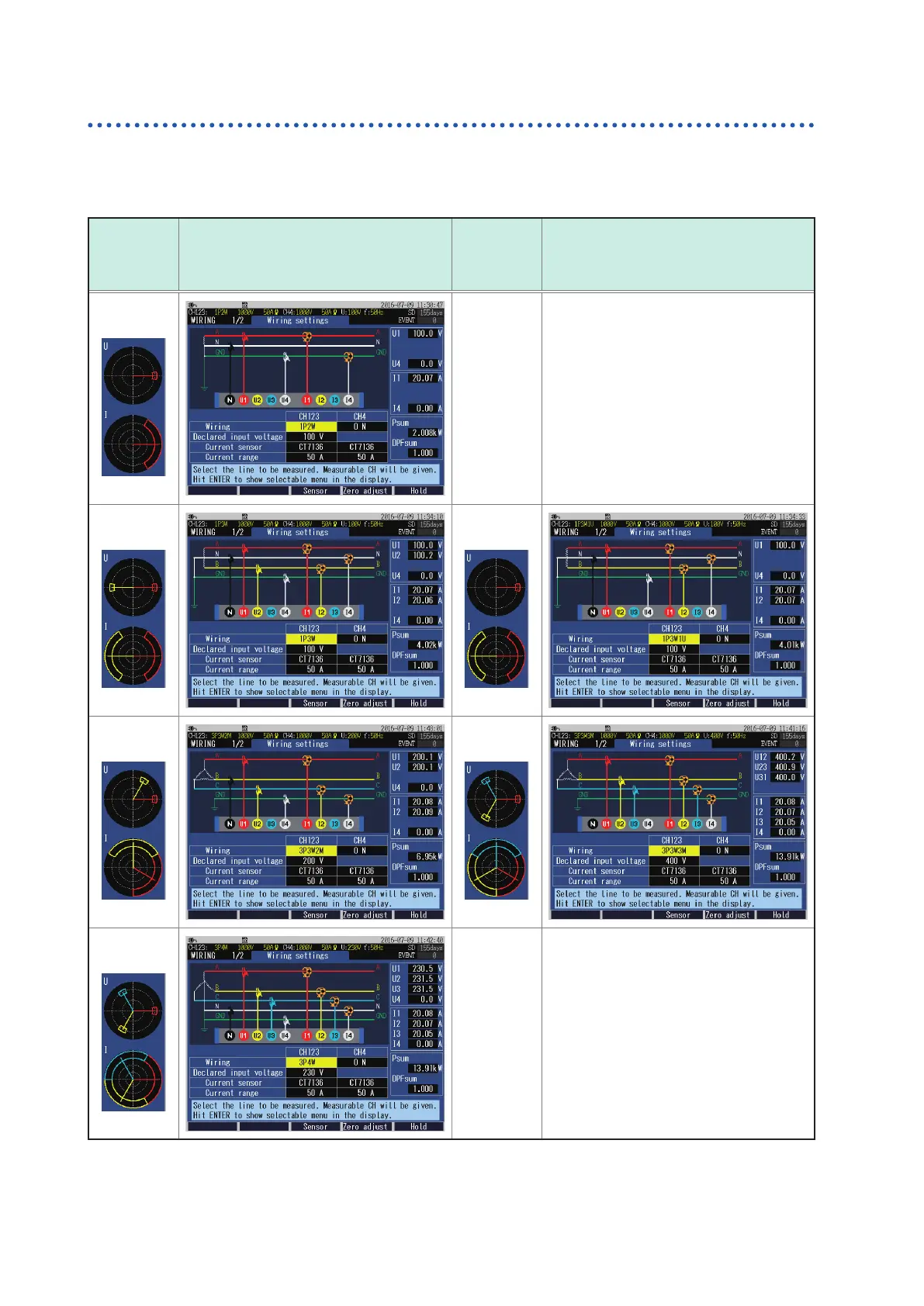
Wiring diagram
The vector diagram in the following screen example shows the measurement line in its ideal
(balanced, power factor 1) state.
Wiring
selection
vector
diagram
Screens
Wiring
selection
vector
diagram
Screens
1P2W
1P3W 1P3W1U
3P3W2M 3P3W3M*
3P4W 3P4W2.5E (Available after the rmware update)
*: If 3P3W3M is selected, do not apply a voltage to CH4 even with CH4 set to ON.

 Loading...


