169
Flagging Concept
35. Current unbalance factor (negative-phase unbalance factor, zero-phase unbalance factor)
measurement specications Iunb, Iunb0
Measurement method Calculated using the fundamental current component of each 3-phase in the 3-phase
3-wire (3P3W2M, 3P3W3M) and 3-phase 4-wire wiring (For details, see Calculation
Formula.).
Displayed items Negative-phase unbalance factor (Iunb)
Zero-phase unbalance factor (Iunb0)
Measurement range Component: A
Unbalance factor: 0.00% to 100.00%.
36. K Factor (multiplication factor) measurement specications KF
Measurement method Calculated using the harmonic RMS current value of 2nd order to 50th order. (For
details, see Calculation Formula.)
Analysis window width 10 cycles/12 cycles
Window point count Rectangular 2,048 points
Displayed items K factor KF
Measurement range 0.00 to 500.00
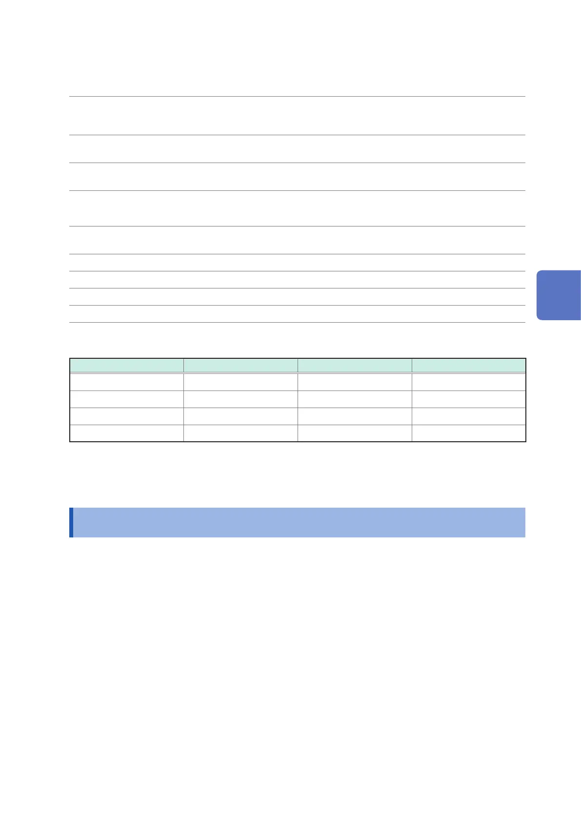
37. RMS frequency characteristics
Frequency Voltage Current Power
40 Hz to 70 Hz Specied as RMS value Specied as RMS value Specied as RMS value
70 Hz to 1 kHz ±3% rdg.±0.2% f.s. ±3% rdg.±0.2% f.s. ±3% rdg.±0.2% f.s.
1 kHz to 10 kHz ±10% rdg.±0.2% f.s. ±10% rdg.±0.2% f.s. ±10% rdg.±0.2% f.s.
40 kHz −3 dB −3 dB -
(Note: While using 2000 A range of Model CT7742, f.s. tolerance of the current and power should be 2.5 times the
value)
14.3 Flagging Concept
IEC61000-4-30 Flagging concept
If an unreliable values are produce during a dip, swell, or interruption, the 200-ms aggregation will be “agged.”
An interval data including the agged 200-ms aggregation will also be agged.
Flagged data are referenced to decide the frequency for an interruption, and are recorded in status information
of the TREND data. If events of a dip, swell, or interruption are set to off, the values are also agged.
14
Specications

 Loading...


