149
Event Output
13.2 Event Output
Outputs a signal to the external device synchronized with an event in the instrument showing that
there is an event.
Application
(1) Connect a warning device.
This is a good way to output warnings when events such as an interruption occurs.
(2) Connect to the trigger input terminal of a Memory HiCorder.
The instrument allows recording waveforms of an event for 200 ms to 11.2 s (1 s before event,
200 ms during the event, and 10 s after event) (see Event waveform recording time before
Event, Event waveform recording time after Event (p. 74)). Use a Memory HiCorder with the
instrument to record waveforms for a longer period.
Setting
See “13.3 External Event Output Settings (SET UP Screen)” (p. 150).
Signal output method
2 “Event output terminal” (EVENT OUT
――――― ― ――
)” and 4 “Ground terminal
for event output (non-isolated) (GND2)” are connected to an
external device.
2 and 4 are isolated from the internal circuit of the instrument.
Connect terminal 2 to an external power supply through a pull-up
resistor as shown in the following circuit diagram.
If an event occurs in the instrument, a pulse signal is output.
1 2 3 4
Hioki
Memory HiCorder
See “13.4 Connection” (p. 151).
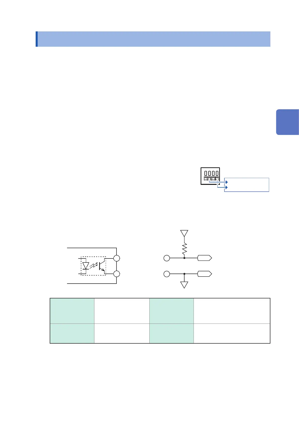
Circuit Diagram
2
EVENT OUT
――――― ― ――
terminal
Power supply (30 V or lower)
Pull-up resistor
(10 k
Ω
recommended)
4
Ground terminal
for event input
(GND2)
<Internal circuit of the instrument>
Photo coupler
<Example of external circuit>
Specications
Output signal Open collector output
Isolated with a photo
coupler
Active Low
Maximum input
current
5 mA
Maximum input
voltage
30 V Pulse width Low level
Short pulse: Approx. 10 ms
Long pulse: Approx. 2.5 s
13
External I/O

 Loading...


