16
Procedure for Investigating Power Quality
(4) What is the expected cause?
• Abnormal voltage
RMS value trends, waveform distortion, transient overvoltage
• Abnormal current
Leakage current, inrush current
Step 3: Checking investigation (measurement) locations (collecting
site data)
Collect information (site data) from as many locations as possible to prepare for the investigation.
Check the following:
(1) Wiring
1P2W / 1P3W /
3P3W2M / 3P3W3M / 3P4W
3P4W2.5E (available after the
rmware update)
(2) Declared input voltage
100 V to 800 V
(3) Frequency
50 Hz/60 Hz
(4) Is the voltage between the neutral line and ground,
and neutral line current required to be measured?
If the measurements are required, CH4 of the wiring settings
should be set to ON. See p. 48, and p. 64.
(5) Current capacity
Current capacity is required to
select current sensors used for
the measurements.
(6) Other items related to the whole facility
• Other systems causing power supply malfunctions
• Principal electrical system operating cycle
• Any additions or changes to facility equipment
• Check of the power distribution system in the
facilities
Step 4: Making measurements with the power quality analyzer
(measurement procedure)
Measurements are performed using the following procedure:
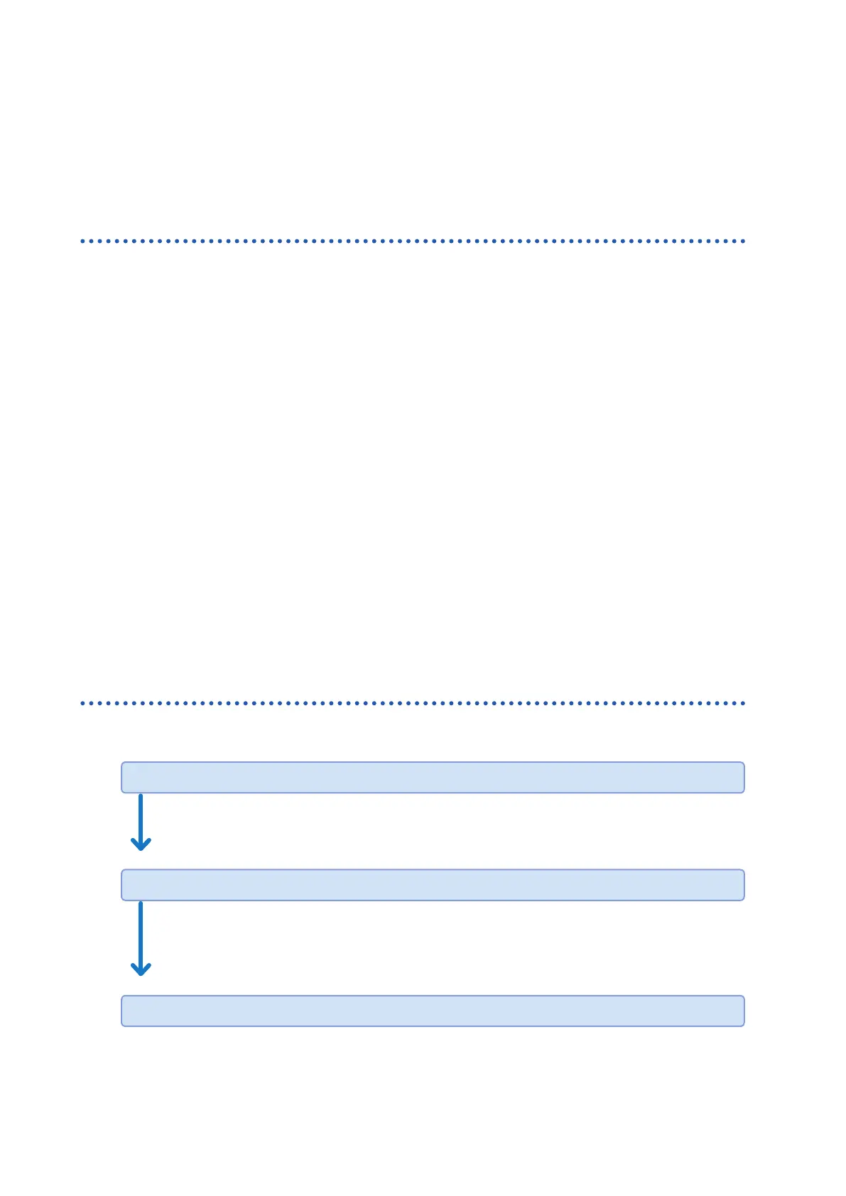
Preparations
Attach accessories and optional equipment required for the measurements to the Power
Quality Analyzer.
See “2 Preparing for Measurement” (p. 35).
Measurement settings/Connections/Wiring*
Congure the conditions required for the measurements and connect voltage cord and
current sensors to the instrument.
Connect the wires to the measuring object and check if there is any mistake.
See “Installation Environment” (p. 7) and “4 Wiring (WIRING Screen)” (p. 47).
Recording settings/Event settings*

 Loading...


