52
Connecting Current Sensors and Conguring Current Sensor Settings
4.4 Connecting Current Sensors and Conguring
Current Sensor Settings
Be sure to read “Handling Cords and Cables” (p. 8).
Connect the optional current sensor to the current input terminal of this instrument.
• To make it easier to identify channels, color-code the cords with colored spiral tubes.
See“Color coding of current sensor (for channel identication)” (p. 36).
• Secure the cords together with a spiral tube if necessary.
See“Bundling the voltage cords and current sensors (If required)” (p. 37).
• Refer to the instruction manual supplied with the current sensor for specication details and
usage procedures.
When measuring power lines that use multiple channels
Use a current sensor of the same model.
Example: Use current sensors of the same model from CH1 to CH3 for the 3-phase 4-wire system.
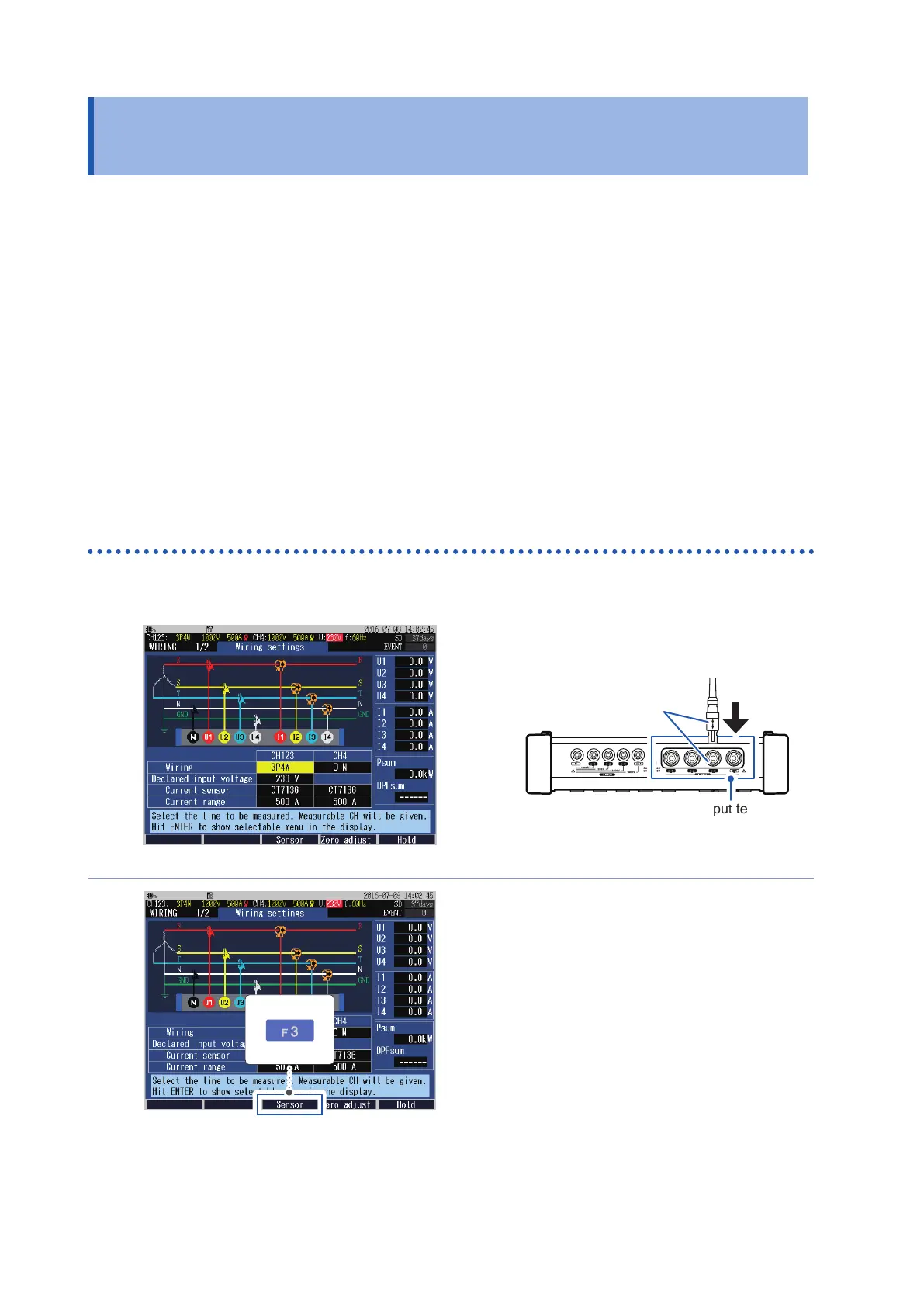
Connecting the optional current sensor
1
Press the [WIRING] key to display the
WIRING, wiring settings screen.
2
Insert the connector of the current
sensor while checking the channel on
the screen.
Current input terminal
Align the arrow with the
concave part of the terminal
to insert the connector.
When disconnecting the current sensor, be sure
to grip the part of the connector indicated by the
arrows and pull it straight out.
3
The current sensor and the maximum current
range are set automatically.

 Loading...


