88
Verifying the Vector
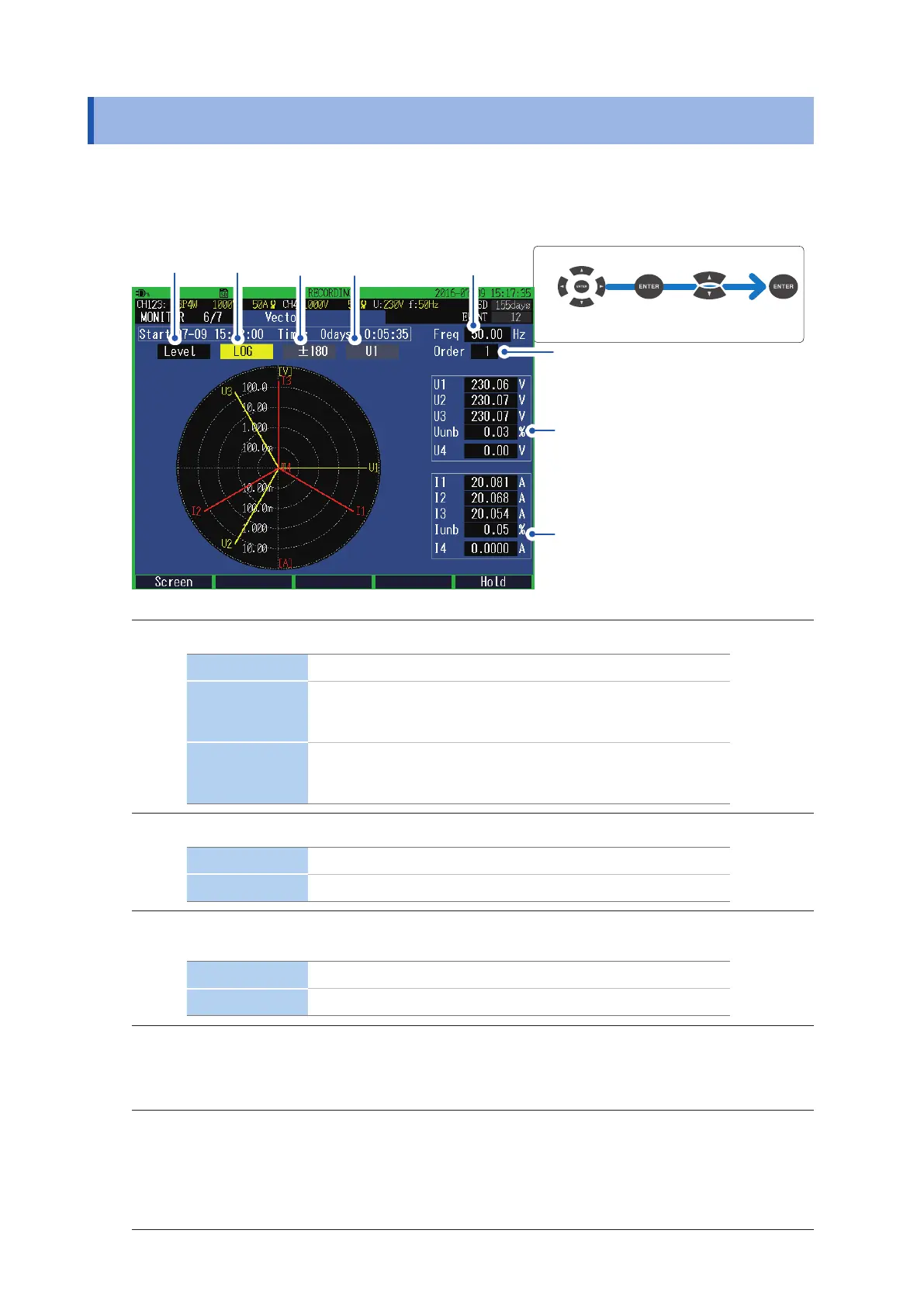
6.6 Verifying the Vector
Press the [MONITOR] key to display the MONITOR, Vector screen.
The voltage and current phase relationships for each harmonic order of the CH1 to CH4 are
displayed in the vector diagram.
Move the cursor
Select
1
Measured value
of frequency
2 3
5
Voltage negative-phase unbalance factor
Current negative-phase unbalance factor
4
1
Enables you to set the numerical values to be displayed.
Level RMS voltage and RMS current
% of FND
Takes the fundamental wave component as 100% and shows a
harmonic of each order in terms of proportion to the fundamental
wave component.
Phase
The phase angle of each harmonic order when the phase of
fundamental wave components of the reference source is
expressed in terms of 0°.
2
Enables you to set the display method of the axes.
Linear Linear display
Log Logarithmic display (low levels also become easily visible.)
3
Enables you to set at the time of Phase display.
Set the display method of numbers of phase angle.
±180 Lead 0 to 180°, lag 0 to −180°
Lag360 Lag 0 to 360°
4
Enables you to set when Lag360 is set.
Select the reference (0°)source.
U1, I1, U2, I2, U3, I3
5
Enables you to set the number of harmonic orders to be displayed.
The values of the frequency, voltage negative-phase unbalance factor (Uunb), and current negative-
phase unbalance factor (Iunb) remain the same as calculated by using the fundamental wave (1st
order).
0 to 50

 Loading...


