990400 Rev C 2010 May 1
C-3
Quick Reference Guide
Implant Planning Screen
• Double click an individual Cross Section to zoom in. Double click again to
reduce to original size.
LABELS:
The following labels on the images help clarify the orientation of the anatomy:
• R: Right Side (Axial, Pan)
• P: Posterior (Axial)
• B: Buccal (Cross Sections)
POP UP MENUS
Right click views to display a Pop Up menu containing a subset of these options:
• HU Statistics
• Distance
• Display Formats: The default is 5 x 2. The other options are 7 x 3 and 3 x 1.
• Set Filters
• Save as JPEG
• Open Output Folder
• Estimate Nerve Canal
CURSOR TOOLS
• All views, except the 3D Model, have Brightness/Contrast, Rotate, Drag,
Zoom and Pan. 3D Model only has Rotate.
• The mouse scroll wheel is active on the Axial Slice Position, 3D Model and
Cross Sections to scroll through slices.
• Back Tool: to exit out of a planning screen back to the Main Display,
move cursor to the very top left corner of screen until X is displayed
and click. Or click the Screen option on the Main Menu bar.
REMINDER
Implant Screen is acquired by
double clicking Panoramic View
from Preview window or selecting it
from the Screen menu.
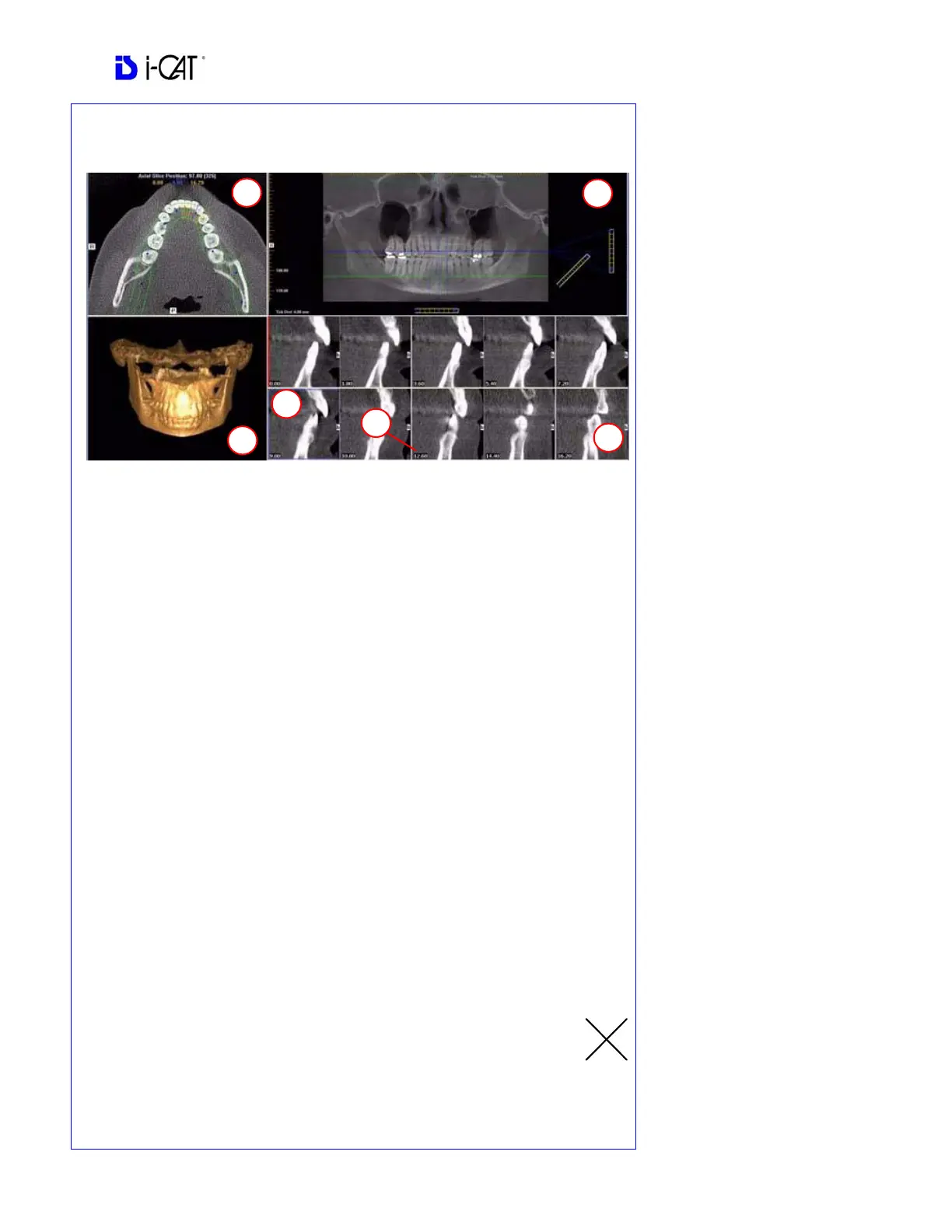
DISPLAYED VIEWS
1. AXIAL SLICE POSITION
2. PANORAMIC MAP
3. 3D MODEL
4. CROSS SECTIONS
5. Center Slice is outlined in Blue.
6. Slice Location Number
Slice Location numbers start at “0”
for center of anatomy or midline.
(The “0” slice is outlined in Red).
All slices to the patient’s right are
negative #’s. All slices to the
patient’s left are positive #’s.
Midline is determined by axial map.