990400 Rev C 2010 May 1
Reconstruction of Anatomy
8-11
Adjusting MIP, Centerline and Image Type
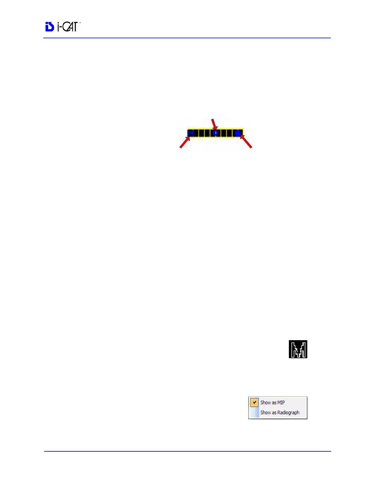
The following slice control bar is found in various views and
positions throughout the system software.
• Center-Line Position - click and drag the Center-Line
Position tool moves the displayed centerline of the selected
image. This changes the selected position of subordinate
images.
• MIP/Radiograph Toggle Control - clicking the MIP/
Radiograph Toggle Control toggles the images displayed
between MIP and Radiograph.
• Slice Thickness Control - click and drag the Slice
Thickness Control right/left increases/decreases slice
thickness and spacing (respectively).
NOTE: The Slice Thickness of each view is at the Voxel size
originally scanned. For example, if scanned at a 0.3 Voxel size, the
slice thickness is 0.3. If scanned at a Voxel size of 0.4, the slice
thickness is 0.4
Selecting MIP or Radiograph Display
The system software enables displaying images as MIP or
Radiograph.
To select the type of image displayed:
1. Move cursor to the top right of any of the image views on the
preview screen. The cursor becomes an M.
2. Click mouse while cursor is an M and the
following popup window appears.
3. Click the menu item corresponding to the
desired image type. (The currently selected image type is
denoted with a checkmark.)
CENTER-LINE
POSITION
SLICE THICKNESS
CONTROL
MIP/RADIOGRAPH
TOGGLE CONTROL