www.izcorp.com • 1.800.776.1356
CONDITION CAUSE SOLUTION
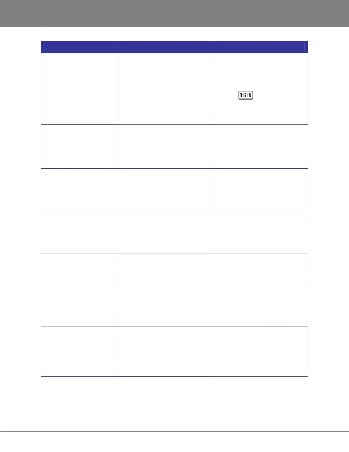
No signal on Digital Input – Faulty Cable or incorrect pin out
– Tracks are not armed
– RADAR Sync not locked
– Input format not set
– RADAR Configured in Dual/Quad
wire mode
– See Wiring Diagrams on
www.izcorp.com
– If Sync light is flashing, check
sync source, or set RADAR as
master
– Press and select format
NONE
– MAIN MENU/IO MENU/DIG IO
SDQ is set to SINGLE
No Signal on Analogue
Output
– Faulty Cable or incorrect pin out
– RADAR Sync not locked
– See Wiring Diagrams on
www.izcorp.com
– If Sync light is flashing, check sync
source, or set RADAR as master
No signal on Digital Output – Faulty Cable or incorrect pin out
– RADAR Sync not locked
– See Wiring Diagrams on
www.izcorp.com
– If Sync light is flashing, check sync
source, or set RADAR as master
Pop and Clicks on Ins/Outs – RADAR Sync not locked or faulty
– Not enough ventilation for RADAR
– If Sync light is flashing, check sync
source, or set RADAR as master
– Allow adequate airflow and cooling
for RADAR
Can’t mount Recording
Drive
– Drive not inserted
– Drive not locked
– RADAR not set to mount that SCSI
ID
– Drive has failed
– Check to see that LED beside the
drive is a solid 0 or 1, and lock the
key
– Check the MODE display ID # on
RADARView is set to the same
ID # as the drive
– MAIN
MENU/DIAGNOSTICS/SCAN
SCSI BUS Is the hard drive
detected on the correct ID#?
Flashing Red Timecode or
ERR in Session Controller
Display
– Recording drive is not rated for
high sample rate
– External SCSI device faulty
– Drive is failing
– Verify using an iZ Technology
recording drive for the project
sample rate
– Remove all other SCSI devices
except for current recording drive
– Replace drive