Group 5 Transport/Start up Page 36
Release R1.03e LEIBINGER JET3
5.4.3 Interface X1 (Encoder)
5.4.3.1 Description and configuration
The interface “X1” provides the connection of a shaft encoder.
Due to the input for which you can set the software individually, the encoders can
be connected according to different norms without an additional converter.
Note:
For variable product speed you have to use a shaft encoder to synchronize
the printing speed or to control the constant font width.
Basic data /Recommended working conditions:
Signal type Parameter Value
Input level
Difference input ≥ +/-200mV
Input voltage range: -0,3 bis 5,5V
Max. frequency 10 MHz
RS422
Terminating resistor 100 Ohm
Input level High 2,4V up to 5,5V
Input level Low -0,5V up to 0,7V
Max. frequency 500 kHz
TTL
Input resistance 1 MOhm
Input level High 12 up to 28V
Input level Low -0,5 up to 3,5V
Max. frequency 500 kHz
HTL
Input resistance 4 kOhm
(1)
All 24V inputs which are designated with (1) are protected by a self-reset fuse with 700 mA.
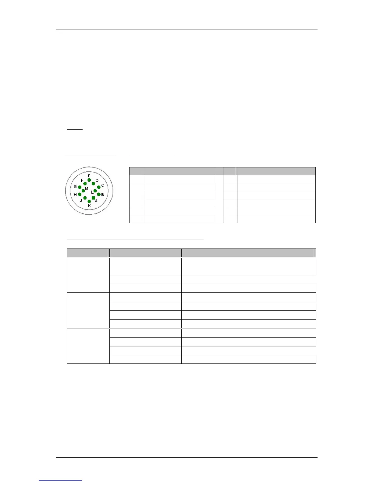
Pin Designation Pin Designation
A +5 V (max. 400 mA) G Encoder port /B RS422
B GND H Encoder port A TTL (5V)
C +24 V
(1)
J Encoder port B TTL (5V)
D Encoder_port A RS422 K Encoder port A HTL (24V)
E Encoder port /A RS422 L Encoder port B HTL (24V)
F Encoder port B RS422
M PowerOn Option
Plug assignment:
Pin connection: