6. Operation
6.1 Construction/Structure of the device
The high-performance LEIBINGER JET3 is manufactured of a solid two parts stainless
steel cabinet. Due to the two parts construction you will get a thermal separation
between the hydraulic- and electronic section. The device consists of the following main
components.
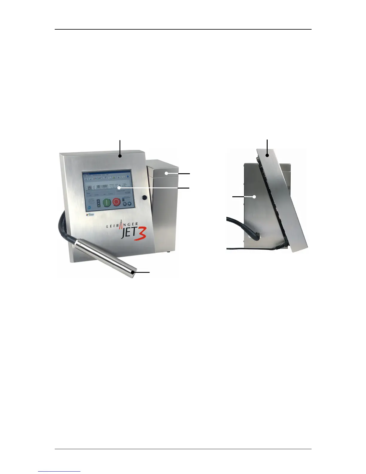
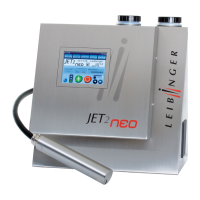
Figure 9
Equipment configuration (General view)
1 – Electronic cabinet 4 – Refilling unit
2 – TFT – Touch Display 5 – Print head with umbilical
3 – Hydraulic cabinet
In the closed electronic cabinet you will find the essential electronic components as
power supply, the TFT-Touch Display as well as the controller board.
The large central arranged TFT-Touch Display describes the interactive interface for the
operator. This central entry medium with its extensive 10,4” color display with backlight
allows a clear, self-explaining operator guidance without additional keys and switches.
In the hydraulic cabinet you find all components which are required for the
transportation and preparation of ink.
The refilling unit provides a supply of consumables. It contains two separate reservoir
tanks for ink and solvent. The unpressurized tanks can be refilled without interrupt
procedure, odorless and splash-free during the operation.