Lenze · 8400 HighLine · Reference manual · DMS 12.0 EN · 06/2017 · TD23 1364
17 Function library
17.1 Function blocks | L_DFSET_1
_ _ _ _ _ _ _ _ _ _ _ _ _ _ _ _ _ _ _ _ _ _ _ _ _ _ _ _ _ _ _ _ _ _ _ _ _ _ _ _ _ _ _ _ _ _ _ _ _ _ _ _ _ _ _ _ _ _ _ _ _ _ _ _
Compensation process
At the input of the second set or actual touch probe pulse, the difference between master and slave
position is detected which is then provided via the nSpeedSetOut_v speed output and equivalently
as position at .
In C01073/1
, the following bit coded settings can be made for the compensation procedure:
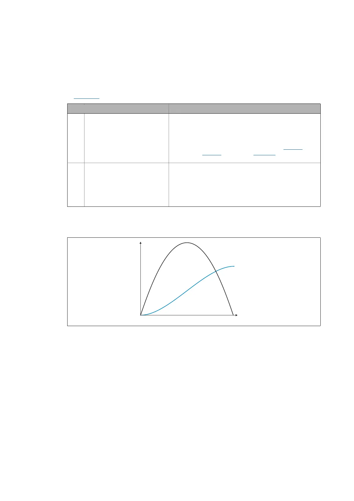
The following illustration shows a compensating process after the marks have been detected. The
speed is added here as a parabola to the line speed. (The scaling in this diagram does not correspond
to reality)
[17-39] Example: Compensation process
setting Info
Bit 1 Angle correction with polynomial If this bit is set (Lenze setting),the compensating movement is
rounded by polynomial.
• The angle error to be compensated is limited to ±1073741823
increments due to the system. This applies in general when the
L_DFSET_1 carries out the compensation.
• The maximum compensating speed can be set in C1069/2
. When
"0" is set in C1069/2
if activated in C01075/1, the angle error is
measured and output to dnPosDiffOut_p.
Bit 2 External angle correction
From version 13.00.00
If this bit is set, the FB L_DFSET_1 does not compensate any angle
errors.
• Every time the angle errors have been measured, the angular
difference is output to dnPosDiffOut_p.
• In addition, a FALSE/TRUE edge is output to bAck. This signal
serves to trigger an external profile generator which
compensates the angular offset via a speed profile additionally.
nSpeedSetOut_v dnPosDiffOut_p
t
v