Lenze · 8400 HighLine · Reference manual · DMS 12.0 EN · 06/2017 · TD23 663
9 Diagnostics & error management
9.9 Error messages of the operating system
_ _ _ _ _ _ _ _ _ _ _ _ _ _ _ _ _ _ _ _ _ _ _ _ _ _ _ _ _ _ _ _ _ _ _ _ _ _ _ _ _ _ _ _ _ _ _ _ _ _ _ _ _ _ _ _ _ _ _ _ _ _ _ _
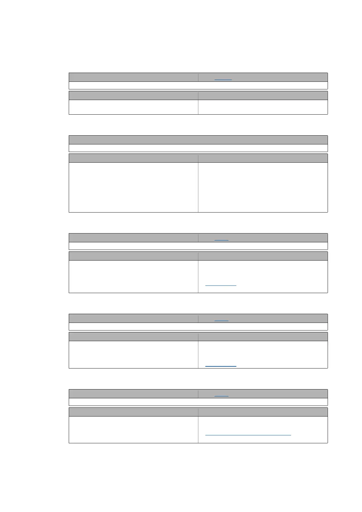
Id5: Pole position identification error [xx.0123.00074]
oC13: Maximum current for Fch exceeded [xx.0123.00090]
ot2: Speed controller output limited [xx.0123.00093]
FC01: Switching frequency reduction [xx.0123.00094]
FC02: Maximum speed for Fchop [xx.0123.00095]
Response (Lenze setting printed in bold) Setting: C00643/1 ( Adjustable response)
0: No Reaction 1: Fault 2: Trouble 3: TroubleQuickStop 4: WarningLocked 5: Warning 6: Information
Cause Remedy
Pole position identification has not been completed
successfully.
Check parameter setting of the pole position
identification.
Response (Lenze setting printed in bold)
0: No Reaction 1: Fault 2: Trouble 3: TroubleQuickStop 4: WarningLocked 5: Warning 6: Information
Cause Remedy
The device has detected a motor current which exceeds
the maximum current limit at permanent switching
frequency of the inverter.
• If a permanent switching frequency inverter is set, a
certain limit arises for the maximum current,
depending on the setting. If this current limit is
exceeded due to a load impulse or overload, an error
message is displayed.
• Observe the maximum current setting depending on
the set switching frequency of the inverter.
• Reduce the required load or setting of the dynamic
switching frequency if necessary.
Response (Lenze setting printed in bold) Setting: C00567 ( Adjustable response)
0: No Reaction 1: Fault 2: Trouble 3: TroubleQuickStop 4: WarningLocked 5: Warning 6: Information
Cause Remedy
The output of the speed controller has reached the
internal limit value. In this status, the speed controller is
not able anymore to correct the system deviation.
• Only during "Closed loop" operation or with vector
control (SLVC).
• Observe load requirements.
• Correct dimensioning or reduce setpoint generation
dynamics if necessary.
Motor control
Response (Lenze setting printed in bold) Setting: C00590 ( Adjustable response)
0: No Reaction 1: Fault 2: Trouble 3: TroubleQuickStop 4: WarningLocked 5: Warning 6: Information
Cause Remedy
Load-dependent switching frequency reduction • Observe load requirements.
• Correct dimensioning or reduce setpoint generation
dynamics if necessary.
Motor control
Response (Lenze setting printed in bold) Setting: C00588 ( Adjustable response)
0: No Reaction 1: Fault 2: Trouble 3: TroubleQuickStop 4: WarningLocked 5: Warning 6: Information
Cause Remedy
Maximum speed for chopper frequency has been
reached.
• The maximum speed has been exceeded depending
on the switching frequency.
Select the correct maximum speed as a function of the
switching frequency.
Motor control: Determine speed limits