Up slow-down switch
RUN contactor feedback
Brake contactor feedback
Inspection up
Inspection signal
Inspection down
Up limit
Down limit
NICE1000
new
CN1
CN6
X1
X2
X3
X4
X5
X6
X7
X8
X9
X10
X11
X12
X13
X14
X17
X18
X19
X20
X21
X22
X23
X24
R
S
T
Three-phase
AC power
supply
Safety
contactor
Braking resistor
+
–
PB
J12
CN12
+24 VDC
Down slow-down switch
Overload
Light curtain
Door close limit
Inspection
circuit
Analog load cell
signal
MCTC-PG
PG card
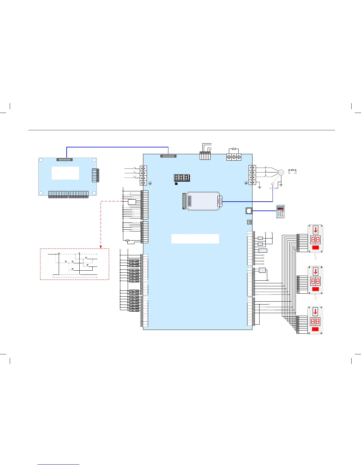
Note:
1. Functions of I/O terminals are set in
parameters of groups F5, F6, and F7.
2. This figure shows only a wiring
example. The wiring method varies with
the type of the display board.
3. The extension board is used only
when the I/O terminals on the MCB do
not meet requirements.
4. The parameter setting is the default.
Set the parameters onsite based on
actual requirements.
Door zone
Inspection
common
Up
Short shaft
safety switches
X4
X5
X6
+24 VDC
Car top
inspection
Emergency electric operation
1 2
3 4
1 2
3 4
1 2
1 2 1 2
1 2
5 65 6
Up
Down
Down
1 2
24V
COM
COM
Fire emergency
Elevator lock
Door open limit
X16
X15
Attendant state
Direction change
Shorting motor stator feedback
Emergency evacuation feedback
M
U
V
W
Encoder
Motor
Braking
mechanism
Shield
RUN
contactor
K2
CAN+
GND
MOD-
MOD+
CAN-
GND
Reserved
Designated for
parallel control
Door 1 open button
Door 1 close button
Door 1 open delay button
Floor 1 door 1 car call
Floor 2 door 1 car call
Floor 3 door 1 car call
Floor 4 door 1 car call
Floor 5 door 1 car call
Floor 1 door 1 up call
Floor 2 door 1 up call
Floor 3 door 1 up call
Floor 4 door 1 up call
Floor 2 door 1 down call
Floor 3 door 1 down call
Floor 4 door 1 down call
Floor 5 door 1 down call
CN5
S1
Cables
RUN contactor output
RUN contactor output COM
Brake contactor output
Brake contactor output COM
Fan/Lamp output
Fan/Lamp output COM
CN9
CN3
CN4
CN2
CN2
CN3
CN4
AI-M
AI
L
1
L
2
L
3
L
4
L
5
L
6
L
7
L
8
COM
24
V
L
11
L
12
L
13
L
14
L
10
L
9
L
23
L
24
L
25
L
26
L
15
L
16
L
17
L
18
L
22
L
21
L
19
L
20
+24 VDC
-24 VDC
Button input
of in-car
operation box
Y
8
Y
9
YM1
Y
10
Y
11
Y
12
Y
13
Y
14
Y
7
Y
6
CN7
Safety circuit
RUN
Brake
-110 VAC+110 VAC
Y
1
M
1
Y
2
M
2
Y
3
M
3
XCM
X
25
X
26
X
27
M
0
Y
0
Door lock circuit 1
Door lock circuit 2
YM
2
Y
17
Y
18
Y
19
Y
20
Y
21
Y
22
YM
3
Y
16
Y
15
Buzzer output
Overload output
BCD code
display board
Reserved
Door 1 open output
Door 1 close output
Low 7-segment a output
Low 7-segment b output
Low 7-segment c output
Low 7-segment d output
Inspection output
CN8
BCD code high-order bit output
Door
machine
Reserved
Reserved
Returning to base floor at fire emergency
Minus sign display output
Down arrow display output
Up arrow display output
+24 VDC
MF.K
RUN
STOP
RES
QUICK
PRG
ENTER
RUN
LOCAL/REMOT FED/REV TUNE/TC
RPM
%
A VHz
CN1
CN10
USB
interface
YM
Y27
Y26
Y25
Y24
Y23
Y5
Y4
L34
L33
L32
L31
L30
L29
L28
L27
L50
L49
L35
L36
L37
L38
L48
L47
L46
L45
L44
L43
L42
L41
L40
L39
Relay
output
Button input and button indicator output
MCTC-KZ-D
extension card
BCD code
display board
BCD code
display board
Top
floor
Bottom
floor
Reserved
Reserved
Reserved
Reserved
Reserved
Reserved
Reserved
Reserved
Reserved
Reserved
Reserved
Power supply
of door
machine signal
Safety/Door lock
circuit COM
Reserved
Reserved
Reserved
Lamp/Fan
running
Segment d
High-order bit
Inspection
Minus sign
display
Up arrow
Down arrow
Segment c
Segment b
Segment a
Segment d
High-order bit
Inspection
Minus sign
display
Up arrow
Down arrow
Segment c
Segment b
Segment a
Segment d
High-order bit
Inspection
Minus sign
display
Up arrow
Down arrow
Segment c
Segment b
Segment a