4-98 Motorola RF Switch System Reference Guide
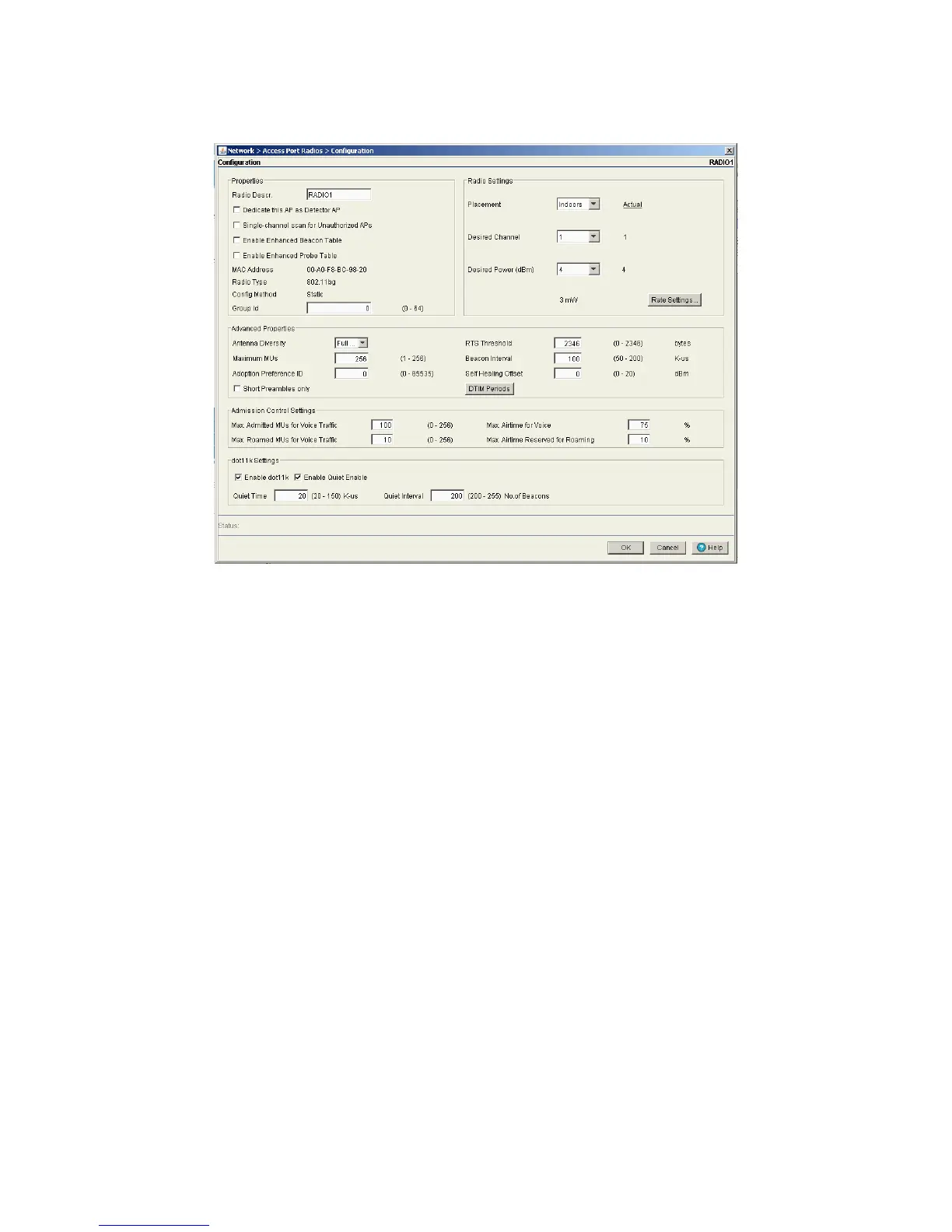
4. Click the Edit button to display a screen containing settings for the selected radio.
5. The Switch field displays the IP address of the cluster member associated with each Access Port radio.
When clustering is enabled on the switch and Cluster GUI is enabled, the Switch field will be available
on the Access Port Radio edit screen. For information on configuring and enabling Cluster GUI, see
Managing Clustering Using the Web UI.
6. In the Radio Descr. field, enter a brief description to differentiate the radio. The description is used to
describe radios of the same type and can be used to locate a radio if there are any problems.
7. Select the Dedicate this AP as Detector AP option to use this radio as a detector port to identify rogue
APs on the network.
Setting this radio as a detector dedicates the radio to detect rogue APs on the network. Dedicated
detectors do not connect to clients.
8. Select the Single-channel scan for Unauthorized APs option to enable the switch to scan for rogue
devices using the radio’s current channel of operation.
9. Select the Enable Enhanced Beacon Table option to allow adopted Access Port or Access Point radios
to scan for potentially unauthorized APs across all bands.
This option utilizes radio bandwidth, but is an exhaustive means of scanning across all available channels
and listening for AP beacon traffic. Once probe responses are received, a network device management
application like Motorola RFMS or the Wireless Intrusion Detection System (WIDS) can locate the device
and remove it if defined as unauthorized.
10.Select the Enable Enhanced Probe Table option to enable an adopted Access Port or Access Point
radio to forward the probes required to obtain MU RSSI information.
RSSI data (as obtained by at least three detecting radios) can be used by the Motorola RFMS application
to triangulate the location of an MU on a site map representative of the actual physical dimensions of
the switch radio coverage area. Once located on a site map, intuitive decisions can be made regarding
the MU’s authorization within the switch-managed network.
 Loading...