5-169
5-13 Safety Function
SYSDRIVE MX2 Series USER'S MANUAL (3G3MX2-Axxxx)
5
Functions
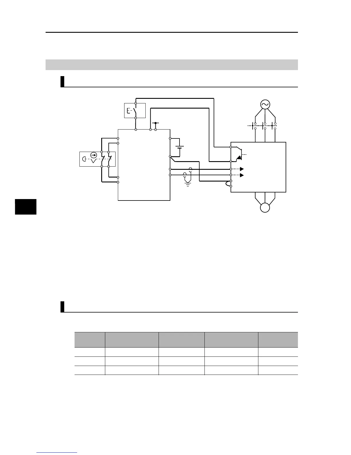
Wiring Example
Wiring Example
Wiring Example When EDM is Used (Conforming to PLd under ISO13849-1)
When the emergency stop button is pressed, the current flowing through GS1 and GS2 is cut
off and the Inverter output is cut off. As a result, the motor enters a free-run status. This
operation corresponds to stop category 0 under IEC60204-1.
Note 1. Shown above are wirings that apply when the multi-function input terminals are used based on
the source logic. If they are used based on the sink logic, the wiring must be changed. For details,
refer to "Connection to Programmable Controller (PLC)" on page 2-22.
Note 2. The safety relay and emergency shutoff input signal line must use a shielded coaxial cable such
as RG174/U (by LAPP) per MIL-C17 or KX3B per NF C 93-550 with an outer diameter of 2.8 mm
and length of 2 m or less. Ground the shield.
Note 3. All inductor parts such as relays and contactors must have an overvoltage protection circuit.
Example of System Components
Shown below is an example of peripherals conforming to the applicable safety standards which
are recommended as system components.
The Inverter meets the PLd safety requirement only when combined with PLd-compliant equipment.
EDM
(feedback) input
3G3MX2
KM1
Safety output
Safety Unit
* Certified under the applicable safety
standards IEC61508, ISO13849.
M
Reset
switch
GS2
GS1
EDM
PC
Safety input
G9SX-GS226-T15-RC
S14
S24
T12
T21
T22
A1
A2
Safety switch
(The figure shows
an emergency-stop
pushbutton switch.)
T11
T31
T32
PSC
SC
+24 V
T33
+24 V
Series
name
Model Manufacturer Applicable standard
Date of
certification
G9SA G9SA-301
OMRON Corporation
ISO13849-2 cat4, SIL3 06.06.2007
G9SX G9SX-GS226-T15-RC
OMRON Corporation
IEC61508 SIL1-3 04.11.2004
NE1A NE1A-SCPU01-V1
OMRON Corporation
IEC61508 SIL3 27.09.2006