3-10
3-3 Test Run
SYSDRIVE MX2 Series USER'S MANUAL (3G3MX2-Axxxx)
3
Operation
3-3 Test Run
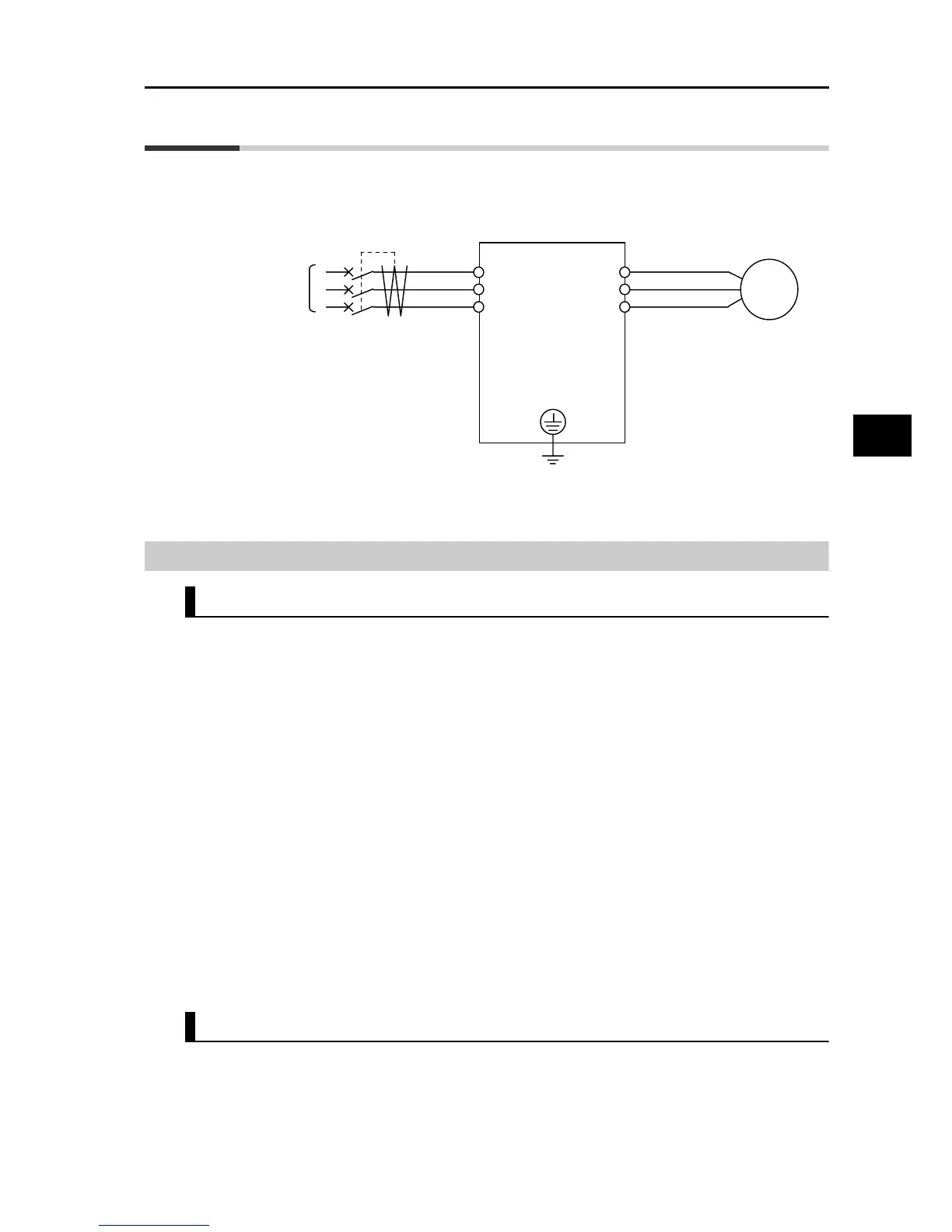
An example of basic connection is given below. Refer to "Operation Method" on page 3-7 when
issuing a RUN command/frequency reference from the control circuit terminal block.
Refer to "Name of Parts of the Digital Operator" on page 3-1 for the parameter setting method.
Procedure for Test Run
Command/Reference Input From the Digital Operator
1. Check if the wires are connected correctly.
2. Turn on the power of the Inverter.
3. Set Frequency Reference Selection (A001) to "02" (Digital Operator).
4. Set RUN Command Selection (A002) to "02" (Digital Operator).
5. Set Output Frequency Setting (F001). It is recommended to set a low speed of approx.
10 Hz first to ensure safety.
6. Set RUN Direction Selection (F004).
7. Display Output Frequency Monitor (d001) and press the Enter key.
Confirm that
"
0.00
"
(Hz) is displayed.
8. Press the RUN key. The RUN (during RUN) LED indicator is lit and the motor starts
to turn.
9. Confirm the output frequency and motor rotation direction displayed on the Digital
Operator, and check if the Invertor is free from errors. For the motor rotation
direction, refer to Rotation Direction Monitor (d003).
10. If no problem is found, gradually increase the output frequency using Output
Frequency Setting (F001).
11. After checking the operation, press the STOP/RESET key. The motor starts to
decelerate and once it stops, the RUN (during RUN) LED indicator turns OFF.
Command/Reference Input From the Control Circuit Terminal Block
1. Check if the wires are connected correctly.
2. Turn on the power to the Inverter.
3. Set Frequency Reference Selection (A001) to "01" (Control circuit terminal block).
4. Set RUN Command Selection (A002) to "01" (Control circuit terminal block).
3-phase power
supply
ELB
R/L1
S/L2
T/L3
U/T1
V/T2
W/T3
Inverter
Motor
M
G