5-157
5-12 Simple Position Control Function
SYSDRIVE MX2 Series USER'S MANUAL (3G3MX2-Axxxx)
5
Functions
5-12 Simple Position Control Function
The following explains the simple position control mode.
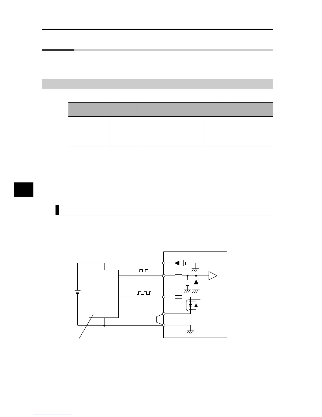
Encoder Connection
The hardware specification for pulse train input is described below.
When this function is used, wire as follows.
Dual-phase Pulse Train
Input the dual-phase pulses to the RP and EB terminals. Since the EB terminal is also used as
multi-function input terminal S7/EB, use all multi-function inputs, including the EB terminal,
based on the source logic (voltage-output encoder or PNP open collector encoder). Also make
sure the input voltage is within the rated range for the multi-function input terminal (18 to 24 V).
Allocate EB to multi-function input terminal S7/EB.
Maximum
frequency
RP terminal
(5 to 24VDC) (32 kHz max.)
S7/EB terminal
(24 VDC) (1.8 kHz max.)
Dual-phase pulse
train input with
90°C phase
difference
(P004 = 01, 02)
to 1.8 kHz
Phase-A pulse train
(PNP open-collector or voltage-
output encoder)
Phase-B pulse train
(PNP open-collector or voltage-
output encoder)
1-phase pulse train
input + direction
(P004 = 03)
to 32 kHz
1-phase pulse train
(PNP open-collector or voltage-
output encoder)
Direction signal
(Sink/source transistor or
selector switch)
1-phase pulse train
input
(P004 = 00)
to 32 kHz
1-phase pulse train
(PNP open-collector or voltage-
output encoder)
−
P24
RP
S7/EB
PSC
SC
GND
A
B
3G3MX2
Encoder
Voltage-output or PNP
open-collector type encoder
Vcc