5-34
5-3 Input/Output Terminals
SYSDRIVE MX2 Series USER'S MANUAL (3G3MX2-Axxxx)
5
Functions
Multi-function Output Terminal Contact Selection
Whether to apply the NO or NC contact output specification can be set individually for each of
multi-function output terminals P1/EDM, P2 and multi-function relay output terminal MA, MB.
Multi-function output terminals P1/EDM, P2 are open-collector output, while multi-function
relay output terminal MA, MB are relay output.
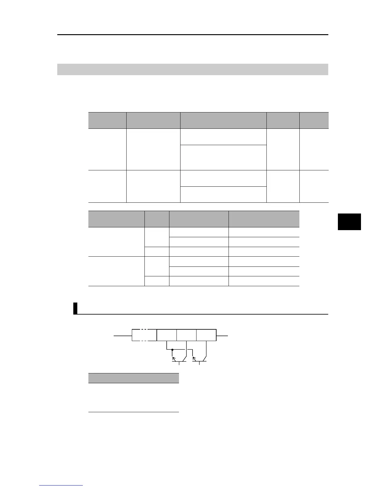
Specifications of Multi-function Output Terminals P1/EDM to P2
Below are the specifications of multi-function output terminals P1/EDM and P2.
Parameter
No.
Function name Data
Default
setting
Unit
C031
C032
Multi-function Output
Terminal P1/EDM
Contact Selection
Multi-function Output
Terminal P2 Contact
Selection
00: NO (NO contact) at P1, P2, MA,
NC (NC contact) at MB
00 −
01: NC (NC contact) at P1, P2, MA,
NO (NO contact) at MB
C036
Multi-function Relay
Output (MA, MB)
Contact Selection
00: NO (NO contact) at P1, P2, MA,
NC (NC contact) at MB
01 −
01: NC (NC contact) at P1, P2, MA,
NO (NO contact) at MB
C031 to C032 set
values
Power
supply
Inverter status Output signal status
00
(NO contact)
ON
Normal OFF (No conduction)
Operating (Error) ON (Conduction)
OFF − Indeterminable
01
(NC contact)
ON
Normal ON (Conduction)
Operating (Error) OFF (No conduction)
OFF − Indeterminable
Electrical characteristics
Between each terminal and PC
Voltage drop 4 V max. at power-on
Max. allowable voltage: 27 VDC
Allowable max. current: 50 mA
PC P2 P1
Inverter interior