5-29
5-3 Input/Output Terminals
SYSDRIVE MX2 Series USER'S MANUAL (3G3MX2-Axxxx)
5
Functions
5-3 Input/Output Terminals
The following explains the Inverter's input/output signals.
Multi-function Input Selection
The following functions can be allocated to any of multi-function input terminals S1 to S7/EB
to operate each function that has been set.
Terminals S1 to S7/EB correspond to C001 to C007.
You can select NO- or NC-contact input for each multi-function input.
The same function cannot be allocated to multiple multi-function input terminals. If the same
function was allocated to multiple functions by mistake, the terminal to which the function was
allocated last becomes effective. no is allocated to all terminals to which the function was
allocated earlier, and their functions are disabled.
After allocating functions to terminals S1 to to S7/EB, make sure that the function settings have
been stored.
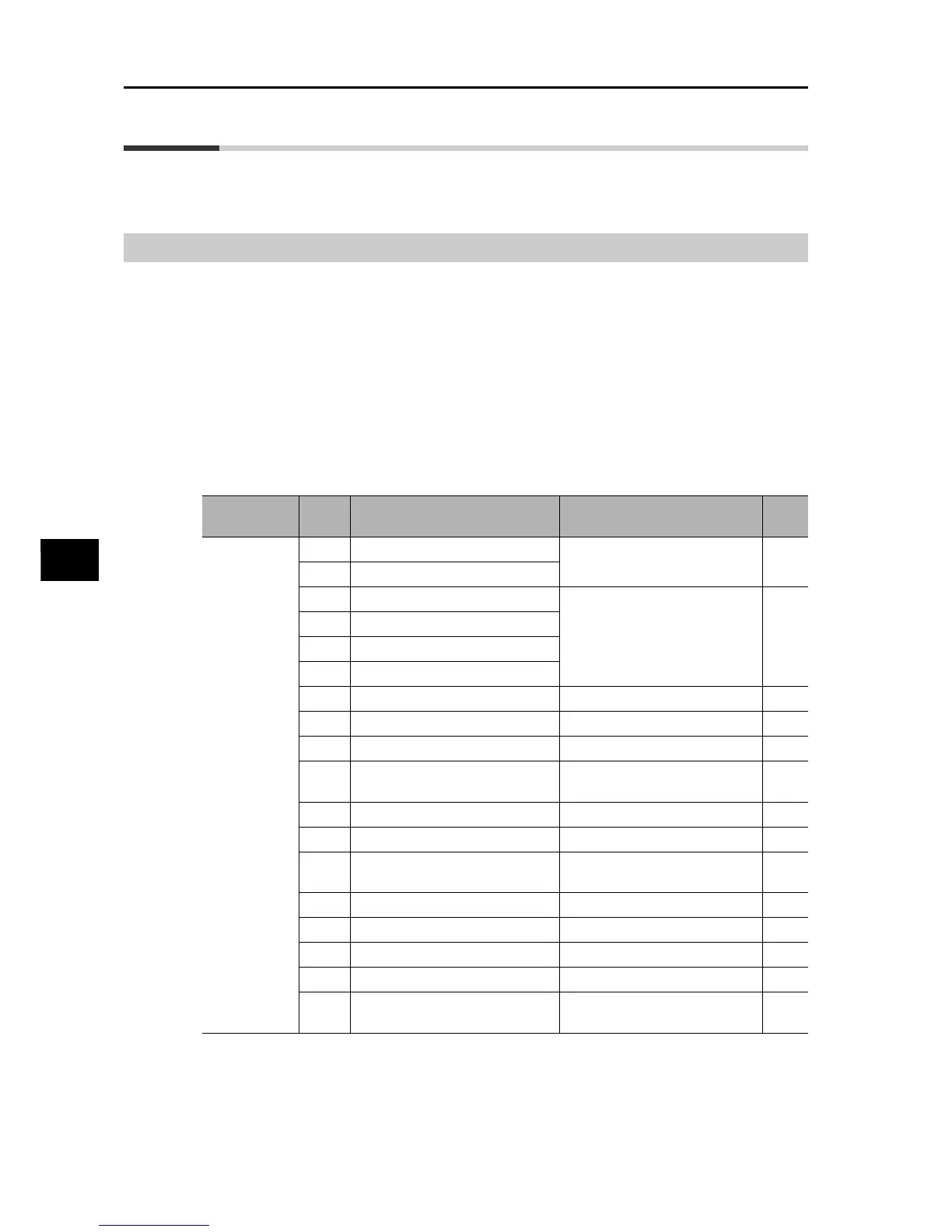
Parameter
No.
Data Description Reference item Page
C001 to C007
00 FW: Forward
RUN Command Selection 5-22
01 RV: Reverse
02 CF1: Multi-step speed 1
Multi-step Speed Operation
Function (Binary)
5-64
03 CF2: Multi-step speed 2
04 CF3: Multi-step speed 3
05 CF4: Multi-step speed 4
06 JG: Jogging Jogging Operation 5-59
07 DB: External DC injection braking External DC Injection Braking 5-135
08 SET: Motor 2 Control Motor 2 Control Function 5-54
09
2CH: 2-step acceleration/
deceleration
2-step Acceleration/deceleration
Function
5-66
11 FRS: Free-run stop Free-run Stop 5-103
12 EXT: External trip External Trip 5-120
13
USP: USP function Power Recovery Restart
Prevention Function
5-105
14 CS: Commercial switch Commercial Switching 5-79
15 SFT: Soft lock Soft Lock 5-84
16 FV/FI: Analog input switch Analog Input 5-37
18 RS: Reset Reset 5-100
19
TH: PTC thermistor thermal
protection
Thermistor Trip Function 5-120