6-4
6-4 Modbus Communication (Modbus-RTU) Protocol
SYSDRIVE MX2 Series USER'S MANUAL (3G3MX2-Axxxx)
6
Communication Function
6-4 Modbus Communication (Modbus-
RTU) Protocol
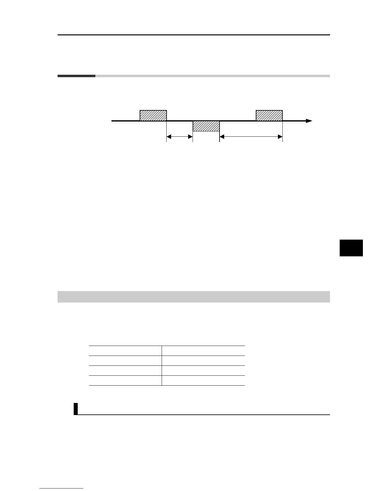
Follow the procedures below in regards to communication between the external control device
and the Inverter.
(1) Frame to be sent from the external control device to the Inverter (Query)
(2) Frame to be returned from the Inverter to the external control device (Response)
(3) Unless the Inverter completes reception of a query from the host within the time set in C077
after the Inverter completes a response (response transmission), the Inverter becomes
ready to receive the first data again. In this case, the Inverter sends no response. Also, the
Inverter's operation conforms to the setting of Operation Selection on Communication
Error (C076). For details, refer to Chapter 4. "Parameter List".
The receiving timeout monitor will be started after the first transmission/reception is
performed after power-on or reset. Timeout will not occur until reception or transmission is
performed.
Response from the Inverter (Frame (2)) will be output as return after the Inverter receives the
query (Frame (1)), not output independently.
The silent interval corresponds to 3.5 characters.
Below is each frame format (command).
Message Structure
A command message sent from the master to a slave is called "Query," while a response
message sent from the slave is called "Response". The query and response transmission
formats are specified below.
Query Response
Slave address
Pre-set numbers ranging from 1 to 247 in each Inverter (slave). (Only the Inverter having the
same slave address as the query will take the corresponding query.)
Broadcasting can be performed by setting the slave address to zero.
A broadcast message is received by all slaves, but the slaves do not return a response.
Wait time
(Silent interval + C078)
Time
Inverter
External control device
(2)
(1)
Communication error timeout time (C077)
(3)
Slave address Slave address for confirmation
Parameter No. Parameter No. for confirmation
Query data Response data
Error check (CRC-16) Error check (CRC-16)