6-10
6-5 Explanation of Each Parameter No.
SYSDRIVE MX2 Series USER'S MANUAL (3G3MX2-Axxxx)
6
Communication Function
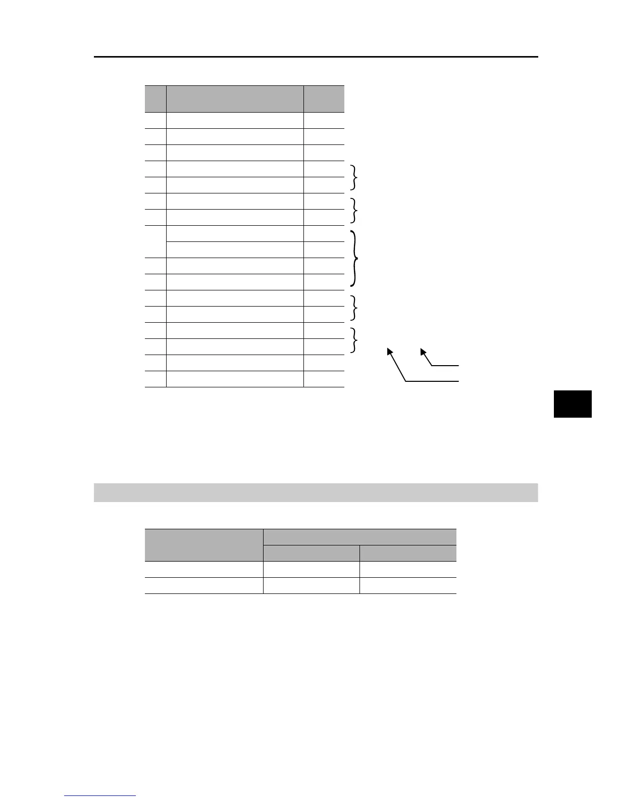
0003h → 03d → E03 (Cause: Overcurrent)
0004h → 4 (Inverter status: Accelerating)
0000 04D2h
→
1234d
→
12.34 [Hz]
(Frequency)
001Eh → 30d → 3.0 [A] (Current)
011Ch → 284d → 284 [V] (DC)
Response:
*1. Broadcasting cannot be performed.
*2. Data is transferred by the number of data bytes. In this example, 12 (0Ch) bytes are used since 6
pieces of holding register data are returned.
*3. Note that the holding register start address is "0011h", which is smaller by 1 than the register number
"0012h". The register number less 1 corresponds to the register address.
Writing Into the Coil [05h]
Writes into 1 coil.The following table shows the coil status change.
Example) Issue a RUN command to the Inverter whose slave address is "1".
The RUN command selection must be set to Communication (A002 = 03).
The coil number of the RUN command is "0001".
"d": Decimal
"h": Hexadecimal
No. Field name
Exampl e
(Hex)
1 Slave address
*1
01
2 Parameter No. 03
3 Number of data bytes
*2
0C
4 Register data 1 (MSB) 00
5 Register data 1 (LSB) 03
6 Register data 2 (MSB) 00
7 Register data 2 (LSB) 04
8 Register data 3 (MSB) 00
9 Register data 3 (LSB) 00
10 Register data 4 (MSB) 04
11 Register data 4 (LSB) D2
12 Register data 5 (MSB) 00
13 Register data 5 (LSB) 1E
14 Register data 6 (MSB) 01
15 Register data 6 (LSB) 1C
16 CRC-16 (MSB) 77
17 CRC-16 (LSB) 3D
Data
Coil status
OFF→ON ON→OFF
Written data (MSB) FFh 00h
Written data (LSB) 00h 00h