2-7
2-2 Wiring
SYSDRIVE MX2 Series USER'S MANUAL (3G3MX2-Axxxx)
2
Design
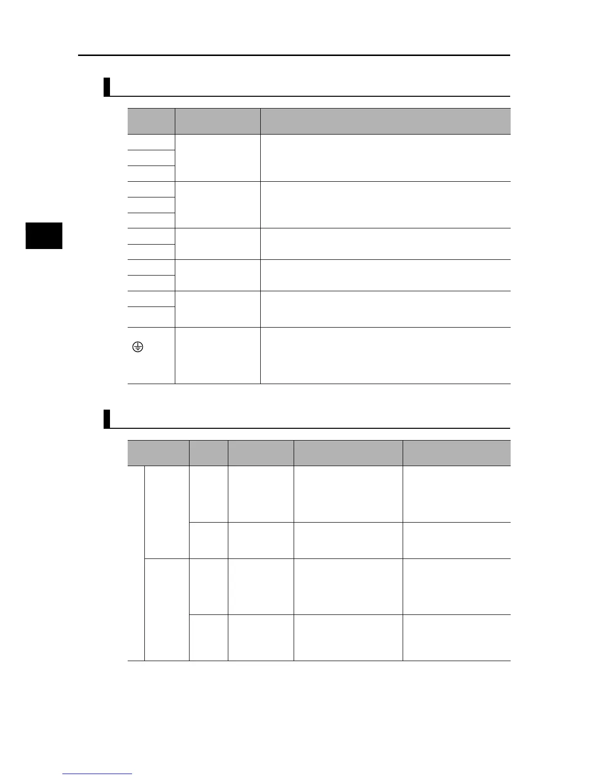
Main Circuit Terminals
Control Circuit Terminals
Terminal
symbol
Terminal name Description
R/L1 Main power supply
input terminal
Connect the input AC power supply.In the case of a 1-phase 200 V
power supply, connect to L1 and N.
S/L2
T/L3
U/T1 Inverter output
terminal
Connect a 3-phase motor.
V/T2
W/T3
+1 DC reactor
connection terminal
Remove the shorting bar between terminals +1 and P/+2, and
connect the optional DC reactor.
P/+2
P/+2 Braking Resistor
connection terminal
Connect optional braking resistors. (If a braking torque is required)
RB
P/+2 Regenerative
braking unit
connection terminal
Connect optional regenerative braking units. (When braking torque
is required or the built-in braking circuit is not sufficient)
N/−
G Ground terminal This is a ground terminal. Connect this terminal to the ground.
Provide Class D grounding for 200 V class models, and class C
grounding for 400 V class models.
On 200 V class models of 3.7 kW or below and 400 V class models
of 4.0 kW or below, the ground terminal is located on the cooling fin.
Terminal
symbol
Terminal name Description Specifications
Analog
Power
supply
SC Input signal
common
This is a common terminal
used by the internal power
supply, digital input and
analog input/output
terminals.
FS Frequency
reference
power supply
10 VDC power supply for
the FV terminal.
Allowable max. current:
7 mA
Frequency
setting
input
FV
Frequency
reference input
terminal (analog
voltage input)
Use this terminal if the
frequency reference is
provided by 0 to 10 VDC
voltage input.
Input impedance
Approx. 10 kΩ
Allowable input voltage
range
−0.3 to +12 VDC
FI
Frequency
reference
terminal (analog
current input)
Use this terminal if the
frequency reference is
provided by 4 to 20 mA
current input.
Input impedance
100 Ω
Allowable input range
0 to 24 mA