3-1
3-1 Name of Parts of the Digital Operator
SYSDRIVE MX2 Series USER'S MANUAL (3G3MX2-Axxxx)
3
Operation
3-1 Name of Parts of the Digital Operator
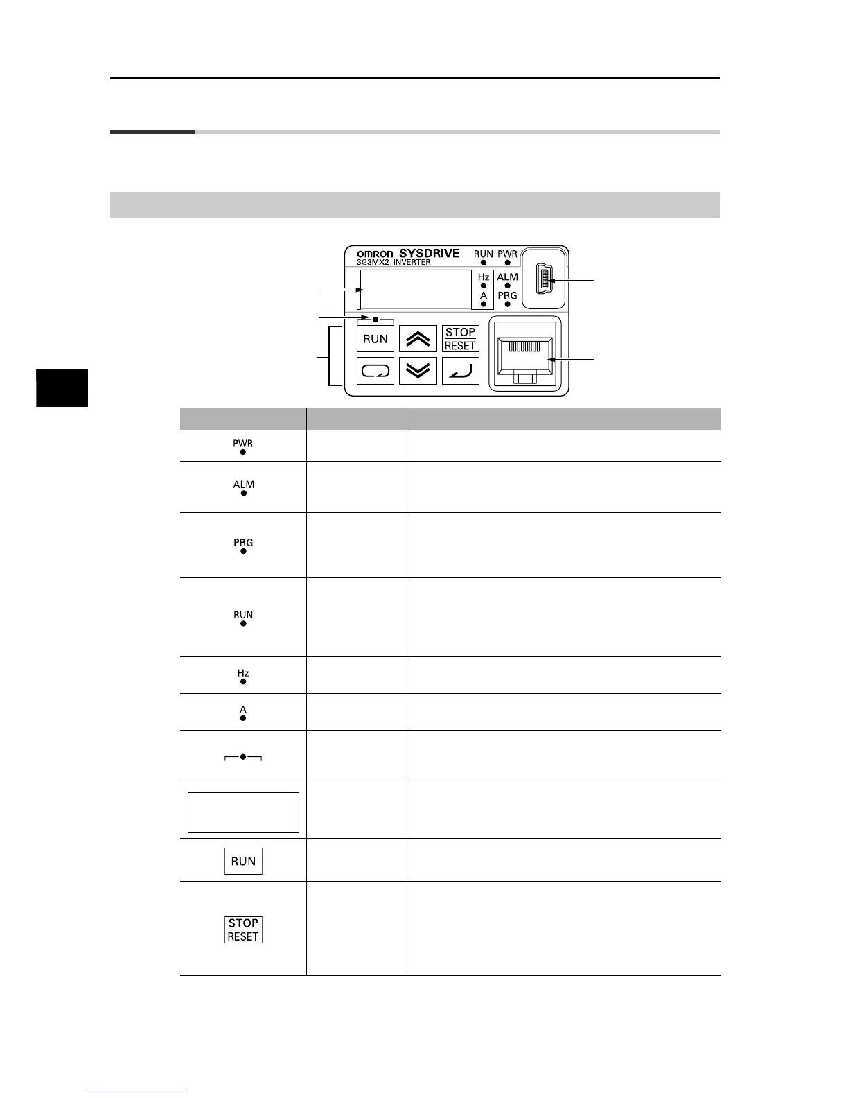
Names of Parts and their Descriptions
8.8.8.8.
Data display
RUN Command enabled
LED indicator
Operation key
USB connector
RJ45 connector
Name Description
POWER LED Lit (green) while the Inverter is receiving power.
ALARM LED Lit (red) when the Inverter trips.
For information on how to reset the trip, refer to "Method for
Resetting Trip" on page 7-1.
PROGRAM LED
indicator
Lit (green) when the displayed data (set value) can be
changed.
Blinks if the set value is invalid. Refer to "Warning Display"
on page 7-6.
RUN (during
RUN) LED
indicator
Lit (green) when the Inverter is running. (Lit when there is
either a "valid RUN command" or "inverter output."
Accordingly, it is also lit when a RUN command is issued at
a set frequency of 0 Hz or while the motor is decelerating
after the RUN command is turned OFF.)
Monitor LED
indicator (Hz)
Lit (green) when the displayed data is frequency.
Monitor LED
indicator (A)
Lit (green) when the displayed data is current.
RUN Command
enabled LED
indicator
Lit (green) when the RUN command is set to the Digital
Operator.
(The RUN key on the Digital Operator is enabled.)
Display Various parameters, frequency/set value and other data are
displayed (red).
RUN key Runs the Inverter. Take note that this key is enabled only
when the RUN command destination is the Digital Operator.
STOP/RESET
key
This key decelerates the Inverter to a stop. (Although the
STOP/RESET key is enabled even when a RUN command is
issued to a destination other than the Digital Operator (factory
default), it can be disabled by a Setting (b087).)
If the Inverter is already tripped, the trip will be reset (return
from the tripping).
8.8.8.8.