3-2
3-1 Name of Parts of the Digital Operator
SYSDRIVE MX2 Series USER'S MANUAL (3G3MX2-Axxxx)
3
Operation
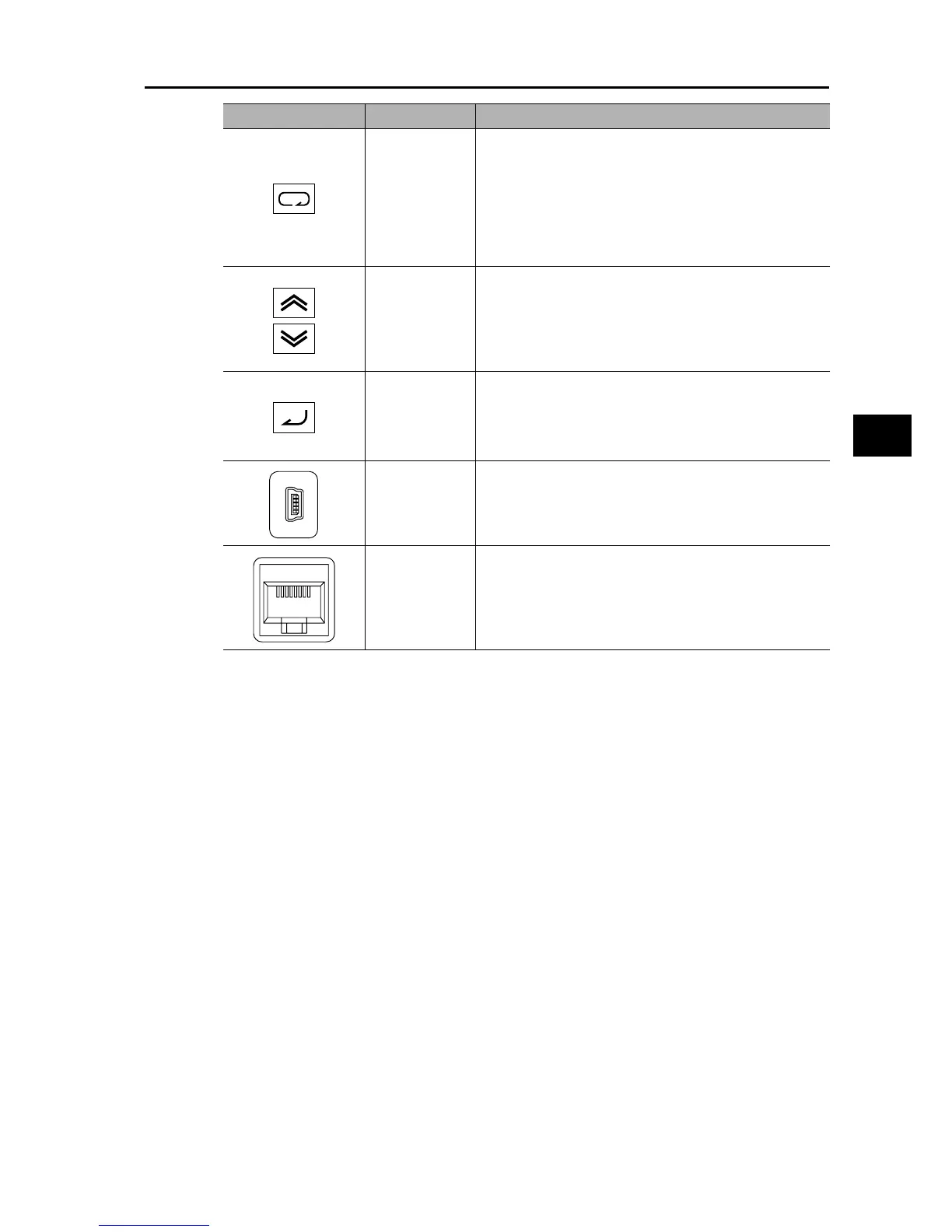
Mode key
Parameter is displayed: Move to the beginning of the next
function group.
Data is displayed: Cancel the setting and return to the
parameter display.
Individual input mode: Move the blinking digit to the left.
Regardless of the displayed screen, pressing and holding
this key (for 1 second or more) displays the data for Output
Frequency Monitor (d001).
Increment key
Decrement key
These keys are used to increment/decrement a parameter
or set data. Pressing and holding each key increases the
incrementing/decrementing speed.
Pressing the Increment and Decrement keys together
activates the "Individual Input MODE" where each digit can
be edited independently.
Enter key Parameter is displayed: Move to the data display.
Data is displayed: Confirm/store the setting (in the
EEPROM) and return to the parameter
display.
Individual input mode: Move the blinking digit to the right.
USB connector
Use this connector (mini-B type) to connect a PC.
The Inverter can still be operated from the Digital Operator
even when it is being operated using a PC, etc., via USB
communication.
RJ45 connector Use this connector (RS-422) to connect the optional
Remote Operator. Once the Remote Operator is connected,
the keys on the main unit become disabled. In this case, use
b150 to set the item to be displayed.
Name Description