2-6
2-2 Wiring
SYSDRIVE MX2 Series USER'S MANUAL (3G3MX2-Axxxx)
2
Design
2-2 Wiring
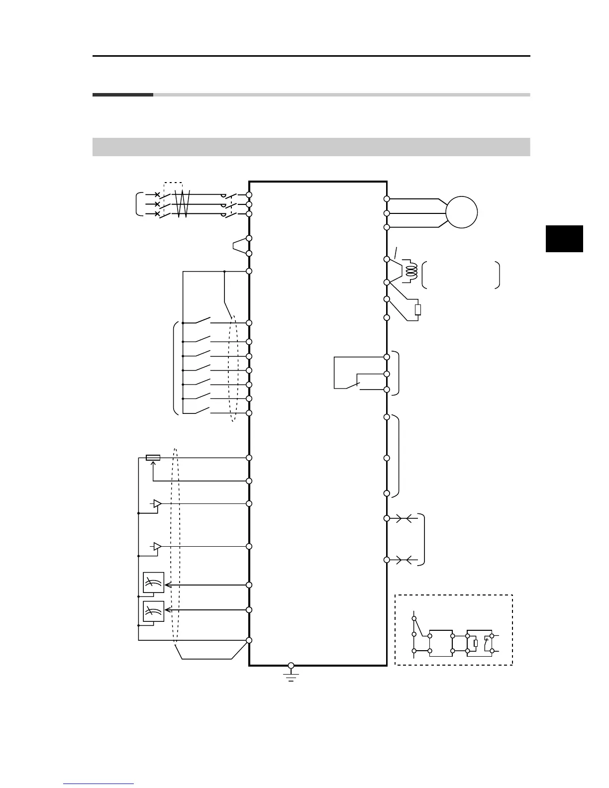
Connection Diagram
Single-phase
3-phase
power
supply
Shorting
bar
Shorting bar
Motor
ELB
MC
R/L1
S/L2
T/L3
24VDC
MC
S7/EB
S5/TH
S4/GS2
S3/GS1
S2
S1
FS
FV
FI
RP
AM
MP
RS−
RS+
PC
P1/EDM
P2
MB
MA
N/−
SC
S6
P24P24
DC reactor
PSC
SC
If any external source-logic
output equipment or power
supply is used, refer to
"Connection to
Programmable Controllers
(PLC)" on page 2-22.
Multi-function
input
(7 contact
points)
Multi-function output
(2 terminals)
Multi-function
relay output
Braking Resistor*1
*1 Option
2 kΩ or more
10 VDC power
supply (7 mA Max.)
Analog voltage input
0 to 10 V (10 bits)
Analog voltage
output 0 to 10 V
(10 bits)
Class D (200 V class)
Class C (400 V class)
Analog current input
4 to 20 mA (10 bits)
Pulse input
5 to 24 VDC
(32 kHz Max.)
Pulse output
0 to 10 VDC
(32 kHz Max.)
Serial communication port
(RS-485/Modbus-RTU)
RB
P/+2
+1
W/T3
V/T2
U/T1
M
To connect the DC
reactor, remove
the shorting bar.
RB
N/
−
P/+2
Regenerative
Braking Unit*1
P
RB
Braking Resistor*1
When using a Regenerative Braking Unit
P
N
Note 1: Connect a single-phase 200 V AC input to terminals L1 and N.
Note 2: Factory default settings for relay output are NC contact for MA and NO contact for MB.